background image


        OFFICINE MARIO DORIN S.p.A.


12 

 
! Attenzione: 
Non  utilizzare  il  compressore 
per 

fare 

la 

carica 

di 

refrigerante nell’impianto. 
 
! Attenzione: 
Prima  di  collegare  i  rubinetti 
alle  tubazioni  assicurarsi  che 
tutti  i  tappi  in  plastica  siano 
stati rimossi.


Evitare  per  quanto  possibile 
l’ingresso 

di 

aria 

nel 

compressore!  Tenere  chiuse 
le 

connessioni 

del 

compressore 

durante 

la 

saldatura  dei  rubinetti  alle 
tubazioni. 
Mantenere  chiusi  i  rubinetti, 
una  volta  rimontati,  finché 
non  si  avvia  la  procedura  di 
messa in vuoto. 
Assicurarsi 

che 

tutte 

le 

tubazioni  e  le  giunzioni  siano 
perfettamente 

pulite 

tenuta. 


Le  indicazioni  relative  alle 
connessioni  standard  sono 
presenti nella figura 3. 

 
!Attention: 
Do not use the compressor to 
fill 

up 

the 

system 

with 

refrigerant


!Attention: 
Before connecting the service 
valves  to  the  pipes  be  sure 
that  all  the  plastic  caps  have 
been taken away. 
Avoid,  as  much  as  possible, 
the 

air 

inlet 

into 

the 

compressor! 
Keep  the  connections  closed 
during  the  welding  of  the 
service valves to the pipes. 
Once the service valves have 
been 

reassembled, 

keep 

them  closed  till  the  vacuum 
procedure 

is 

not 

implemented.


Make  sure  all  the  piping  and 
junctions  are  perfectly  clean 
and sealed. 


The 

indications 

regarding 

standard 

connections 

are 

shown in figure 3. 

 
! Achtung: 
Verwenden  Sie  den  Verdichter 
nicht 

um 

die 

Anlage 

mit 

Kühlmittel zu füllen. 
 
! Achtung: 
Bevor  Sie  die  Absperrventile  an 
die 

Rohre 

anschließen, 

überprüfen 

Sie, 

dass 

alle 

Plastikstöpsel  entfernt  worden 
sind. 
Verhindern 

Sie 

soweit 

wie 

möglich den Lufteingang in den 
Kompressor!  Halten  Sie  die 
Verdichter 

Verbindungen 

während 

des 

Anlötens 

der 

Ventile 

an 

die 

Rohre 

geschlossen. 
Halten 

Sie 

die 

Ventile 

geschlossen 

nachdem 

Sie 

diese  wieder  montiert  haben 
und 

solange 

nicht 

die 

Evakuierung  eingeleitet  worden 
ist. 
Überprüfen  Sie,  dass  alle  Rohre 
und  Verbindungsstellen  perfekt 
sauber und dicht sind. 

 
Angaben 

bezüglich 

der 

Standardverbindungen  sind  in 
Abb. 3 geschildert. 


Collegamenti  

elettrici 


Electrical 

connections 


Elektrische Anschlüsse 


Il 

collegamento 

all’alimentazione 

elettrica 

deve  avvenire  aprendo  la 
scatola  attacchi  elettrici  e 
collegando 

le 

fasi 

di 

alimentazione,  il  conduttore 
equipotenziale ed i conduttori 
per  i  segnali  dei  sensori  di 
temperatura 

secondo 

le 

indicazioni riportate all’interno 
del coperchio della scatola e 
sulla 

targhetta 

del 

compressore. 
Collegare  elettricamente  la 
resistenza 

carter, 

laddove 

prevista, 

le 

altre 

apparecchiature elettriche. 
 
La  targhetta  posta  su  ogni 
compressore  riporta  i  valori  di 

The  connection  to  the  power 
supply  has  to  be  made  by 
opening  the  box  of  the 
electric  connections  and  by 
connecting  the  phases  of 
power 

supply, 

the 

equipotential  wire  and  the 
wires  for  the  signals  of  the 
temperature sensors following 
the 

instructions 

provided 

inside  the  lid  of  the  box  and 
on the compressor plate. 
 
Connect 

the 

carter 

resistance,  whenever  it  is 
provided, 

and 

the 

other 

electric equipments. 
 
The plate positioned on each 
compressor 

shows 

the 

Der Anschluss an das Stromnetz 
erfolgt 

durch 

Öffnen 

des 

elektrischen  Schaltkastens  und 
Anschließen 

der 

Stromzufuhrphasen,  der  Erdung   
und 

der 

Melder 

der 

Temperatursensoren 

gemäß 

den  Angaben,  die  auf  der 
Innenseite  des  Kastendeckels 
und 

auf 

dem 

Typenschild 

angebracht sind. 
Schließen 

Sie 

die 

anderen 

elektrischen  Geräte  und  die 
Ölheizung  des  Kurbelgehäuses 
an, wo diese vorgesehen sind. 
 
Das  Typenschild  das  auf  jedem 
Verdichter  angebracht  ist,  gibt 
Angaben  über  die  Spannung 
und  die  Motorfrequenz  an: 

Summary of Contents for H1000CC

Page 1: ...ISTRUZIONI D USO COMPRESSORI SEMIERMETICI OPERATING INSTRUCTIONS SEMI HERMETIC COMPRESSORS BEDIENUNGSANLEITUNG FÜR HALBHERMETISCHE VERDICHTER ...

Page 2: ...lation Installation 9 Collegamenti elettrici Electrical connections Elektrische Anschlüsse 12 Messa in servizio Commissioning Inbetriebnahme 14 Accessori Accessories Zubehörteile 17 Manutenzione Maintenance Wartung 19 Emergenze Emergency Notfälle 20 Dismissione Dismantling Demontage 21 Avvertenze Warning Hinweise 22 Prospetto anomalie Failures chart Fehlerliste 23 Figure Figures Abbildungen 30 ...

Page 3: ...responsability for the damages caused to people or to things because of the non conformity with the instructions this handbook provides Officine Mario Dorin S p A reserves the right to update this publication at any time or to change the components of this unit if this is considered as necessary for manufacturing or commercial needs The partial or total reproduction of these instructions is forbid...

Page 4: ...liance with the Low Voltage Directive 2006 95 EC The compressor is excluded from Pressure Equipment Directive 97 23 EC art 1 3 10 The compressor is in compliance with the standard EN 12693 2008 The installer of the compressor inside the refrigerant system is obliged to follow the relevant provisions of the law in the installation country making reference to the electrical systems and to the air co...

Page 5: ... and health Nevertheless there is still a series of other risks and for them it is absolutely necessary for the user to implement the safety measures complementary to those technically already applied to the compressor INSIDE PRESSURE Before starting the maintenance of the compressor take away the pressure inside by acting on both taps Do not remove those parts of the compressor subject to an insi...

Page 6: ...sor in places that are not accessible to the staff who does not know about the risks or block their access by means of fences SKIN IRRITATIONS Caution the compressor is shipped with a charge of oil Avoid the direct contact with the skin and the eyes since it is irritant ASPHYXIA HFC and HCFC refrigerants are not toxic or injurious or explosive but can cause asphyxia in case of system leak into a n...

Page 7: ...ine ELECTRICAL CURRENT The danger of electrocution exists when you are in contact with the electrical terminals The lid of the box for the electrical connections prevent this contact Do not feed electrically the compressor till the lid of the box is not completely closed and integral HOT COLD SURFACE The temperatures of the compressor surfaces are such to cause burns for heat or for cold LIFTING P...

Page 8: ...preso tra 5K e 30K Il refrigerante utilizzato deve avere un contenuto di umidità inferiore a 10 ppm È vietato l utilizzo al di fuori del campo operativo e dei The compressor consists of a framework hosting the electric engine inside and the mechanical part of the piston compression The engine which is suitably connected to the power supply triggers the crank gear and the pistons that allow by mean...

Page 9: ...ype and quantity of oil loaded at the factory For any possible topping up and or replacement of the lube use the type indicated on the plate only COMPRESSOR IDENTIFICATION Each compressor is identified thanks to a serial number reproduced on the metal plate riveted in compliance with the EN 12693 regulation this plate specifies Manufacturer s name Compressor model Serial number Manufacture date Ma...

Page 10: ...NER BETRIEBSDRUCK UND PSS MAXIMAL ZUGELASSENER DRUCK BEI STILLSTAND GEMÄß DIN EN12693 Bei Mitteilung an Officine Mario Dorin ist es wichtig auf die Seriennummer des Verdichters hinzuweisen um das Produkt richtig und schnell identifizieren zu können Installazione Installation Installation ATTENZIONE Qualora l imballo risulti danneggiato e o sussistano comunque dubbi sulla integrità del compressore ...

Page 11: ...r In both cases the machine has to be accessible to the authorized staff only Install the compressor in a horizontal position on the appropriate vibration dampers see figure 2 The compressor can work also with inclination in respect to longitudinal and or transversal axis different from zero and dependent on compressor model for further information please contact our technical customer service AIR...

Page 12: ...r Weld the service valves to the system pipes Reassemble the service valves on the compressor Check the leaks from the pipes by means of a pressure test with N2 or dry air following all the required safety procedures such as for example the use of a pressure reducer placed between the bottle and the system and leaving the compressor service valves closed ATTENTION During this test do not overcome ...

Page 13: ...ohre geschlossen Halten Sie die Ventile geschlossen nachdem Sie diese wieder montiert haben und solange nicht die Evakuierung eingeleitet worden ist Überprüfen Sie dass alle Rohre und Verbindungsstellen perfekt sauber und dicht sind Angaben bezüglich der Standardverbindungen sind in Abb 3 geschildert Collegamenti elettrici Electrical connections Elektrische Anschlüsse Il collegamento all alimentaz...

Page 14: ...ximum working FLA and start up current LRA shown on the nameplate as well as in the catalogues and in the selection software Attention Take the suitable safety measures for the electric power supply against the protection from indirect contacts depending on the distribution system and the earth resistance or the impedance of the earth fault ring i e high sensitivity differential switch For diagram...

Page 15: ...wer supply voltage but fed only through the motor protection electronic module REL available on demand for protections such as thermistor vice versa for protections such as thermik the use of REL is not necessary and the contacts shall be connected in series with the other system protections Achtung Falls PWS Teilwicklungsanlauf Motoren verwendet werden beachten Sie die richtige Sequenz der Phasen...

Page 16: ...perating passing by or staying close to the machine Check the oil level and verify that the oil level is between the levels clearly indicated on the oil sight glass as shown in the following figure OIL LEVEL INDICATION During the first hours of operation of the compressor check the oil level several times Warning If oil have to be added use the type indicated on the nameplate and do it gradually c...

Page 17: ...ice valves and on suction line Excessive foam formation on lubricant visible through warning light Low temperature of surface of oil sump COMPRESSORS REPLACEMENT A particular attention shall be paid in case a compressor is replaced with another one as a matter of fact in the plant a certain oil quantity could have been left such as to cause liquid slugging at the start It could be necessary to rem...

Page 18: ...u richiesta si possono fornire resistenze per tensioni diverse o di potenze diverse si veda la pagina web www dorin com Avvertenza Prima di alimentare la resistenza carter assicurarsi che la tensione sia quella corretta e che la resistenza sia inserita e bloccata Compressors can be equipped with some accessories such as CRANKCASE HEATER It is recommended to fit an oil heater in the compressor cran...

Page 19: ... CHECK On the compressor equipped with oil pump it is installed as standard except on the range H4 where is an option an oil differential pressure switch that measure pressure difference from low pressure side on the crankcase and discharge pressure of the pump The differential pressure switch can be connected to the low pressure connection located on the carter of all compressors and to the press...

Page 20: ...ary to interrupt the main power supply of the system Install on the power supply line a switch selector that can be padlocked place it in an open condition 0 and padlock it during the maintenance After the installation in case of interventions requiring the dismantling of parts of the compressor or for its dismantling it is necessary to start the compressor depressurization according to the follow...

Page 21: ...ten die sich unter Spannung befinden Wiederholen Sie keinesfalls ein Wiederherstellen des elektrischen Schutzes nach einem Kurzschluss Vor einem Neustart der Anlage muss der Fehler beseitigt werden und es müssen alle Teile ersetzt werden die beschädigt sein könnten KONTROLLE IN REGELMÄßIGEN ABSTÄNDEN Kontrollieren Sie den Ölstand Entnehmen Sie eine Öl Probe und überprüfen Sie dessen gute Qualität ...

Page 22: ...me indicato al capitolo Trasporto e posizionamento Attention The compressor can be under pressure Danger of serious burns Wear protective gloves and glasses When the system is no longer used it shall be made inoperative by properly eliminating materials In compliance with the standards in force in the different countries regarding the waste disposal and the respect of the environment the parts of ...

Page 23: ...sembly action or modification made on any DORIN product can affect product compliance to the aforesaid directives OFFICINE MARIO DORIN S p A will not recognize guarantee product conformity to the aforesaid directives whenever the products are overhauled from DORIN itself Consequently we inform you that if necessary the compressor must be serviced and repaired only by OFFICINE MARIO DORIN S p A The...

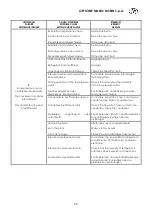
Page 24: ...Reset durchführen Connessioni elettriche allentate o collegamento difettoso Electrical connections loosened or connection defective Elektrische Verbindungen sind locker oder defekte Verbindung Serrare le connessioni Controllare il collegamento con il corretto schema Tighten the connections Check the connection with the correct diagram Alle Verbindungen nachziehen Kontrollieren Sie die Verbindung a...

Page 25: ...rollieren Sie die Einstellung und die Montage de Schalters Condensatore insufficiente o sporco Condenser insufficient or dirty Verflüssiger ungenügend oder verschmutzt Controllare la portata d aria o d acqua al condensatore Pulire il condensatore Check the flow rate of air or water to the condenser Clean the condenser Kontrollieren Sie die Luft oder Wasserzufuhr zum Verflüssiger Reinigen Sie den V...

Page 26: ...heads and check the valve plate and the valves Zylinderköpfe abmontieren und die Ventilplatte sowie die Ventile kontrollieren Trafilamento dalla valvola di sicurezza interna Leakage from internal safety valve Leck des inneren Sicherheitventils Sostituire la valvola Replace the safety valve Das Ventil ersetzen Perdite dalla guarnizione della testa Leakage from the gasket of the head Leck der Zylind...

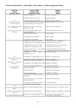
Page 27: ...Flüssigkeit im Kurbelgehäuse Non funziona l evaporatore The evaporator does not work Verdampfer funktioniert nicht Verificare Check Kontrollieren Portata d acqua eccessiva al condensatore Excessive water flow rate to the condenser Übermäßige Wasserzufuhr zum Verflüssiger Regolare la valvola dell acqua Adjust the water valve Regeln Sie das Wasserventil Il rubinetto di scarico è parzialmente chiuso ...

Page 28: ...ck zu niedrig Filtri disidratatori sporchi Deshydrators filters dirty Schmutzige Trocknungsfilter Sostituire i filtri Replace filters Filter ersetzen Battiti dovuti alla presenza di liquido nel compressore Beats due to liquid in the compressor Schläge wegen Flüssigkeit im Kompressor Vedere N 6 See N 6 Siehe N 6 Battiti dovuti all eccesso di olio nel compressore Beats due to excess of oil inside th...

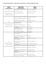
Page 29: ...g verhindert einen richtigen Rückfluss des Öles Controllare le tubazioni Check the pipes Rohrleitungen kontrollieren 10 Pressione dell olio insufficiente o livello dell olio basso Insufficient oil pressure or low oil level Unzureichender Öldruck oder niedriger Ölstand Filtro olio sporco Oil filter dirty Schmutziger Ölfilter Sostituire il filtro Replace the filter Filter ersetzen Eccessiva pression...

Page 30: ... is defective Der Motor ist defekt Controllare gli avvolgimenti Check the windings Die Wicklungen kontrollieren Mancanza di fase Lack of one phase Phase fehlt Controllare la tensione ai 3 terminali Check the tension on the terminals Die Spannung an den 3 Phasen kontrollieren 12 Il compressore funziona con la corrente di rotore bloccato The compressor run with locked rotor amps Der Verdichter läuft...

Page 31: ...nt Ventilplatte ersetzen den Verdichter kontrollieren und die Anwesenheit von Bruchstücken im Kompressor und in der Anlage kontrollieren 14 La temperatura del compressore è elevata The temperature of the compressor is too high Erhöhte Temperatur des Verdichters Rapporto di compressione troppo elevato Compression ratio too high Kompressionsverhältnis zu hoch Controllare i pressostati la pulizia del...

Page 32: ...i Operative Operative Instructions Bedienungsanleitung 31 Figure Figures Abbildungen Fig 1 Sollevamento tramite golfare Lifting point use Anheben mittels Hebering H40CC H8001CC K10000CC K15000CC TANDEM TANDEM HI ...

Page 33: ...OFFICINE MARIO DORIN S p A 32 Fig 2 Impiego degli antivibranti Vibrational dampers use Anwendung der Schwingungsdämpfer H40CC H8001CC K10000CC K15000CC ...

Page 34: ... H751CC 2 28s 22s 94 H751CS H801CC 2 35s 28s 94 H850CS 2 5 35s 22s 117 H1000CC 2 5 35s 28s 136 H1000CS H2400CC 2 5 42s 28s 145 H851CS H1001CS H1501CS 2 5 35s 28s 132 H1501CC H2001CC H2201CC 2 5 42s 28s 137 K1500CS K2500CC 3 5 42s 28s 180 K2500CB K3000CC 3 5 54s 35s 184 H2000CS H2500CC 3 5 42s 28s 190 H2500CS H3000CC 3 5 54s 28s 194 H2700CS H3400CC 3 5 54s 35s 196 Y3060CB Y4060CB Y4560CB 6 5 54s 35...

Page 35: ..._____________________________________ A CC models only B Normal operation C Head fan ______________________________________________ A Uniquement modèles CC B Application standard C Avec ventilateur de culasse ______________________________________________ A Nur CC Modelle B Standard Einsatz C Zylinderkopfbelüftung ______________________________________________ _____________________________________...

Page 36: ...Istruzioni Operative Operative Instructions Bedienungsanleitung 35 Abb 5 Istruzioni montaggio resistenza carter Mounting instructions crankcase heater Montageanleitung der Ölheizung ...

Page 37: ...enza carter DL Rubinetto compressione SL Rubinetto aspirazione Oil sight Oil charge plug Low pressure tap High pressure tap Oil drain plug M8 Crankcase heater Discharge service valve Suction service valve Ölschauglas Ölfüllschraube Niederdruckanschluss Hochdruckanschluss Ölablaßschraube M8 Ölheizung Druckabsperrventil Saugabsperrventil H2 H2 H1 ...

Page 38: ... M10 F Resistenza carter DL Rubinetto compressione SL Rubinetto aspirazione Oil sight Oil charge plug Low pressure tap High pressure tap Oil drain plug M10 Crankcase heater Discharge service valve Suction service valve Ölschauglas Ölfüllschraube Niederdruckanschluss Hochdruckanschluss Ölablaßschraube M8 Ölheizung Druckabsperrventil Saugabsperrventil H32 H34 H32 H34 ...

Page 39: ...ght Oil charge plug Low pressure tap High pressure tap Oil drain plug M10 Crankcase heater Discharge service valve Suction service valve Ölschauglas Ölfüllschraube Niederdruckanschluss Hochdruckanschluss Ölablaßschraube M8 Ölheizung Druckabsperrventil Saugabsperrventil H35 H41 H35 H41 L mm H851CS 640 H1001CC H1001CS H1501CC 680 H1501CS 640 H2001CC 680 H1601CS H2201CC H41 Modello Model Modell Serie...

Page 40: ...resa pressione olio DL Rubinetto compressione SL Rubinetto aspirazione H4 Oil sight Oil charge plug Low pressure tap High pressure tap Oil drain plug M10 Crankcase heater Oil return Oil pressure tap Discharge service valve Suction service valve Ölschauglas Ölfüllschraube Niederdruckanschluss Hochdruckanschluss Ölfüllschraube M10 Ölheizung Ölrückführung Öldruckanschluss Druckabsperrventil Saugabspe...

Page 41: ...ne SL Rubinetto aspirazione Oil sight Oil charge plug Low pressure tap High pressure tap Oil drain plug M10 Crankcase heater Oil return Oil pressure tap Max disch temp sensor Oil diff Pressure switch Gas equalisation Discharge service valve Suction service valve Ölschauglas Ölfüllschraube Niederdruckanschluss Hochdruckanschluss Ölablaßschraube M10 Ölheizung Ölrückführung Öldruckanschluss Sensor de...

Page 42: ...etto compressione SL Rubinetto aspirazione Oil sight Oil charge plug Low pressure tap High pressure tap Oil drain plug M10 Crankcase heater Oil return Oil pressure tap Max disch temp sensor Oil diff Pressure switch Gas equalisation Discharge service valve Suction service valve Ölschauglas Ölfüllschraube Niederdruckanschluss Hochdruckanschluss Ölablaßschraube M10 Ölheizung Ölrückführung Öldruckansc...

Page 43: ...SL Rubinetto aspirazione Oil sight Oil charge plug Low pressure tap High pressure tap Oil drain plug M10 Crankcase heater Oil return Oil pressure tap Max disch temp sensor Oil diff Pressure switch Gas equalisation Discharge service valve Suction service valve Ölschauglas Ölfüllschraube Niederdruckanschluss Hochdruckanschluss Ölablaßschraube M10 Ölheizung Ölrückführung Öldruckanschluss Sensor der m...

Page 44: ...lio H Presa pressione olio DL Rubinetto compressione SL Rubinetto aspirazione Oil sight Oil charge plug Low pressure tap High pressure tap Oil drain plug M10 Crankcase heater Oil return Oil pressure tap Discharge service valve Suction service valve Ölschauglas Ölfüllschraube Niederdruckanschluss Hochdruckanschluss Ölablaßschraube M10 Ölheizung Ölrückführung Öldruckanschluss Druckabsperrventil Saug...

Page 45: ... HI240CC I 460 230 315 170 183 M8x1 25 1 22s 16s 50 HI400CC II 551 347 345 295 250 M8x1 25 2 28s 16s 94 HI550CC II 551 347 345 295 250 M8x1 25 2 35s 22s 96 HI700CC II 551 347 345 295 250 M8x1 25 2 42s 28s 98 HI750CC II 551 347 345 295 250 M8x1 25 2 42s 28s 100 HI1000CC II 645 422 380 284 270 M8x1 25 2 5 42s 28s 135 HI1500CC II 645 422 380 284 270 M8x1 25 2 5 42s 28s 143 Modello Model Modell Forma ...

Page 46: ...Istruzioni Operative Operative Instructions Bedienungsanleitung 45 TANDEM TANDEM HI ...

Page 47: ... 590 1680 305 13 TY9060CC 1800 550 650 1680 305 13 TY9060CB 1800 550 650 1680 305 13 TY10060CC 1800 550 650 1680 305 13 TY9480CB 1800 550 650 1680 305 13 TY10080CC 1800 550 650 1680 305 13 TY10080CB 1800 550 650 1680 305 13 TY11080CC 1800 550 650 1680 305 13 TY11080CB 1800 550 650 1680 305 13 TY12080CC 1800 550 650 1680 305 13 TY12080CB 1800 550 650 1680 305 13 TY15080CC 1800 550 650 1680 305 13 T...

Page 48: ...P H A B Φ kg mm mm kg 2S 1200 650 520 455 325 330 10 5 3 5 35 22 180 2S 1500 650 520 455 325 330 10 5 3 5 35 22 187 2S 2000 650 520 455 325 330 10 5 3 5 35 22 190 2S 2500 755 560 475 380 305 10 5 6 5 42 35 235 2S 3000 755 560 475 380 305 10 5 6 5 42 35 236 2S 3500 755 560 475 380 305 10 5 6 5 42 35 256 2S 3700 755 560 475 380 305 10 5 6 5 42 35 261 Modello Model Modell Dimensioni Dimensions Abmess...

Page 49: ...OFFICINE MARIO DORIN S p A 48 NOTE ...

Page 50: ...Istruzioni Operative Operative Instructions Bedienungsanleitung 49 NOTE ...

Page 51: ...OFFICINE MARIO DORIN S p A 50 1LTG664_05 ...

Reviews: