AC217 KEYPAD SPECIFICATIONS
Power:
Operation voltage – 12/24 Volts AC/DC. No jumper needed to
set voltage.
Stand-by current drain – 10mA @ 12VDC
Active current drain (press keypad key) – Under 30mA.
Active current drain (relay activated) – Under 80mA.
Outputs:
Relay output – 5A @ 28VDC, Form “C”, NO/C/NC,
programmable for 1 to 999 second timed output or shunt
(start/stop) output. Three terminals.
Tamper output – NC output. Connect to tamper circuit of
alarm control panel. Two terminals.
Inputs:
Power – 12/24Volts AC/DC. Two terminals.
Egress – NO, ground (-). Single terminal.
Code Operation:
Up to 100 user codes, 10,000 possible user code combinations.
Max. 10 seconds to enter each digit.
Max. 30 seconds to enter each code.
FACTORY DEFAULTS:
Master Code
0000
User Code Length
4 to 8 Digits
Main Relay Output Time
1 second
Wrong Code Lockout
10 attempts – 30 second
Output Activation Announcement ON
User Code Entry Mode
Manual
Keypress Beep
ON
Silent Operation
OFF
1. Programming Mode N/A
ON
2. Successful Key Entry 1 Beep
1 Flash
3. Successful Code Entry 2 Beeps
2 Flashes
4. Unsuccessful Code Entry 5 Beeps
5 Flashes
5. Master Code Reset Continuous Continuous
(Jumper not replaced)
6. In Stand-by Mode
N/A
1 Flash every 2 seconds
7. Output Relay Activated 1-sec. beep N/A
STATUS
BUZZER
LED (Amber)
MASTER CODE BYPASS (LPJ JUMPER)
If the master code is forgotten or does not work, use the jumper “LPJ” to override the faulty code and permit direct
access into the programming mode as follows:
Disconnect the power supply.
Move the “LPJ" jumper from OFF to ON.
Reconnect the power supply. The keypad will start beeping
Move the “LPJ” jumper back to the OFF position. The keypad will stop beeping as soon as the jumper is removed.
The keypad is now in the programming mode, ready to receive new programming data.
Tamper
N/C
(+)
(-)
(+)
(-)
12VDC
Power
Supply
N/C
N/O
OUTPUT 1
EG
COM
or
Electric
Lock
(+)
(-)
N/O
N/O
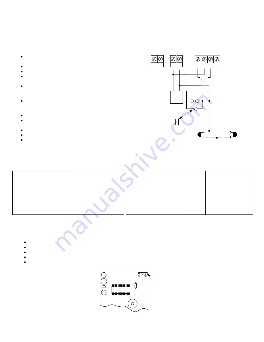
REMARKS:
Output relay
N/O output for fail-secure lock
N/C output for fail-safe lock
Additional egress buttons can be
connected in parallel as needed
(for DC
use only)
Diode
1N4004
Cathode
Use only with
Electric Strike
Egress button (inside the
protected premises)
SAMPLE WIRING INSTALLATION:
12/24V AC/DC
LPJ JUMPER
P:\INSTALLATION INST\DORMA\INST-AC217 (version 2).vsd REV A 08-09 Page 2


