

DORMA
ED 200 ESR
WN 056461 45532
06/12
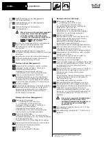
Open valves 3 and 4.
Fix slide channel to door leaf.
Slide channel installation (hinge side)
Marking on axle :
L = axle extension for left-handed
(ISO 6, CCW closing) doors
R = axle extension for right-handed
(ISO 5, CCW closing) doors
Fit axle extension into arm. Ensure that the position of
the square section insert relative to the arm is correct.
Tap the axle extension home using a rubber mallet,
hammer and wooden block or similar.
Prepare slide channel for installation.
Close valves 3 and 4.
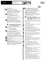
Position arm at an angle of 45° to door frame and fit
over operator axle with cheese head screw and washer
to prevent it from slipping off.
Rotate arm 90°
in hinge direction (preload).
Leave arm in this position. Pay attention to the cam on
the side of the passive door leaf.
Remove arm from axle, refit at original position (45° to
door leaf) and fix with cheesehead screw, washer and
spring washer.
Fit slide channel over slide shoe.
Open valves 3 and 4.
Slide channel is automatically pushed against door
leaf.
Fix end caps on slide channel. Fix slide channel to door
leaf.
Close the door leaves. Check the position of the cam
on the axle of the valve for the door coordinator.
The track roller of the arm has to be located in the
dent of the cam. If not:
Relax the cam.
Turn the cam until the track roller of the arm is
located in the dent of the cam. Screw down the cam
tight. Check position of valve for proper fit. Relax
screws if required. Adjust the valve so that the track
roller rests against the cam without pressure.
Retighten the valve for the door coordinator
thoroughly.
When it comes to fire and smoke doors, fix the cam as
indicated in instructions 054850 45532.
Adjust the closing force via the adjustment screw (not
with size EN 7). When it comes to the ED 200 with
factory-fitted control unit, this unit has to be removed
if required. The admissible force at the main closing
edge of the door has to be limited to 150 N.
1)
A closing force that is adjusted too high
could cause the injury of people. The closing
speed of the active door leaf must only be
adjusted while the passive door leaf is closed.
Adjust closing speed in the range of 115
0
- 25
0
via
valve 3.
Adjust backcheck in the range of 25
0
- 0
0
via valve 4.
Dimensional drawing: Installation on push side
(opposite hinge side) with standard arm
Dimensional drawing: Installation on push side
(opposite hinge side) with slide channel
Dimensional drawing : Installation on pull side
(hinge side) with slide channel
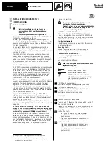
Standard setting on delivery is for right-handed
(DIN-R, ISO 5, CW closing) doors
To fit the operator to a left-handed door, the
microswitch and the cam must be refitted on the
other end of the axle.
Pull out the plastic nut and unscrew the end cap.
In the case the complete system can be
installed direct, attach it to the mounting
screws. Fix the system with at least 6 screws
(template/dimensional drawing) per operator
and go on with picture or .
Relax the valve on the side of the passive door leaf
from its fixing bracket, attach the transportation
safety lock, then remove the screws that fix the
operator to the mounting plate.
Fit the bracket with at least 6 screws
(template/dimensional drawing) per operator.
Screw down the operator to the bracket tightly, then
pull out the transportation safety lock and screw
down the valve for the door coordinator.operator to
the auxiliary mounting screws.
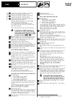
Arm installation (opposite hinge side)
Connect the two components of the standard arm.
Fit axle extension into arm. Ensure that the position
of the square section insert relative to the arm is
correct.
Tap the axle extension home using a rubber mallet,
hammer and wooden block or similar.
Place the main arm onto the drive axle so that it is at
right angles to the door frame, and secure with
washer, spring washer and cheesehead screw.
Secure the arm fixing bracket with two screws to the
door leaf.
Wind or unwind the adjustment screw so that, when
the arm sections are connected, the lower arm is at
right angles to the door.
Clip main arm and lower arm together.
Secure the adjustment screw with the lock nut.
Slide channel arm installation (opposite hinge side)
Marking on axle:
L = axle extension for left-handed
(ISO 6, CCW closing) doors
R = axle extension for right-handed
(ISO 5, CCW closing) doors
Fit axle extension into arm. Ensure that the position
of the square section insert relative to the arm is
correct.
Tap the axle extension home using a rubber mallet,
hammer and wooden block or similar.
Prepare slide channel for installation.
Close valves 3 and 4.
Position arm at an angle of 45° to door frame and fit
over operator axle then fix with cheesehead screw,
washer and spring washer. Pay attention to the cam
on the side of the passive door leaf.
Fit slide channel over slide shoe and fix end caps on
slide channel.
4a
5c
6
7a
7b
4c
5ab
4b
7c
8c
8ab
0
6
13
10a
8a
9a
10c
11c
12c
12a
11a
10b
11b
12b
15
18
17
16
8b
9b
8c
9c
1 )
1 )
1 )
1 )
1 )
As specified in the German guidelines for power-operated
windows, doors and gates


