

DORMA
ED 200 ESR
WN 056461 45532
06/12
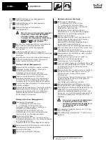
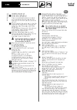
Installation of control unit
Control unit A = Standard unit
Control unit B = Enhanced unit
Screw in screw and washer assembly in cylinder
unit. Put all cables to the front. Push the PCB
holder and the control unit below the screw heads
and fix it.
Fix the connectors. Please refer also to connection
diagrams/wiring diagrams for the following points.
Connect the cable of the program switch to the
control unit.
Connect additional components to the control unit
when available. Please consider connection
diagrams/wiring diagrams for this.
Adjust door opening angle: Move door leaf to
required open position and adjust black cam using
pin supplied until the cam activates the
microswitch. Fix cam in this position.
Switch must be activated at an angle less
than 115° (max. door opening angle) to
allow motor pump to switch off.
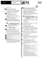
When using control unit „B“ adjust mode switch:
A = single leaf operation
B = double leaf operation
C = application with motor lock
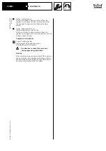
Set both mains ON/OFF switch 1 and program
switch 2 to "OFF".
Connect to mains.
Unlatch Emergency pushbutton ( usually next to
door).
Set mains ON/OFF switch 1 to "ON".
Set programme switch 2 to "AUTOMATIC".
Activate operator by means of eg. radar or
pushbutton, and check performance. Adjust
settings as required.
Opening speed adjustable at valve 1 in the range 0
o
- 75
o
.
Backcheck action adjustable at valve 2 in the
range 75
0
- 115
0
.
Adjust hold-open time by potentiometer in the
range from 0 - 30 secs.
Note:
For the door to reach the open position, the
hold-open time must be adjusted to a larger value
that the total time set at valves 1 and 2. The hold-
open time starts with the activation signal.
0
7
23
22
19
20
21
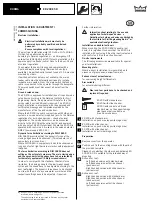
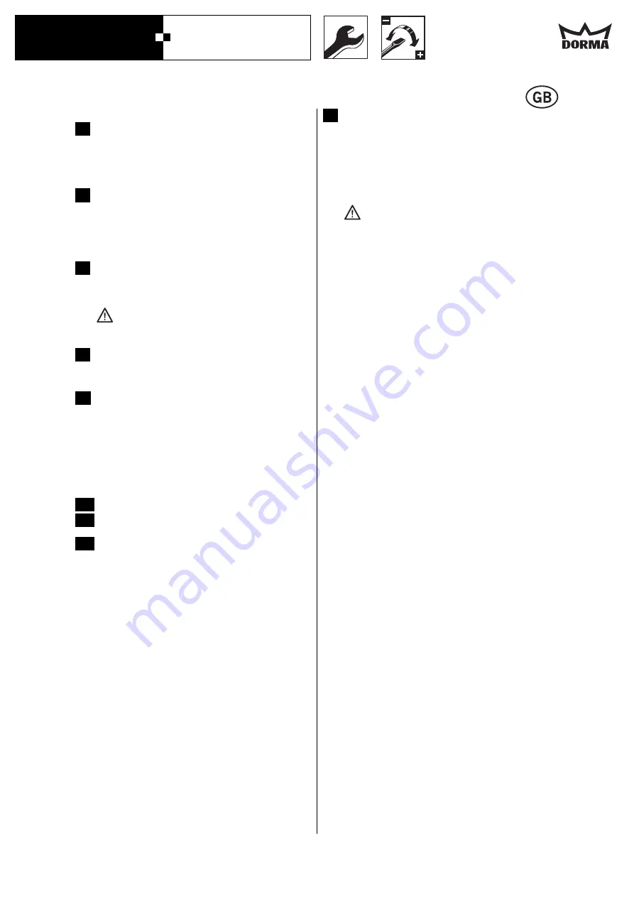
Optional IRS safety sensor on hinge-side.
If necessary use white cam to adjust the blanked
range of the IRS sensor (i.e. area for which sensor is
disabled). Turn the cam with the pin supplied until
the microswitch is activated. Ensure that the position
of the black cam remains unchanged.
Note:
As the door opens to this point, the hinge-side
IRS sensor ceases to operate so that the door is not
tripped by obstacles in the blanked range.
Ensure that the white cam, once adjusted,
does not also activate the limit switch in the
“Door Closed” position.
Sensors in accordance with the relevant installation
instructions.
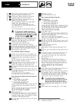
Functional tests
Possible program switch settings:
Programme switch integrated in ED 200:
AUTOMATIC - OFF - PERMANENT OPEN
External programme switch:
OFF - EXIT ONLY - PERMANENT OPEN - AUTOMATIC
(only possible with control unit B).
Check internal activator.
Door opens after signal emission in “AUTOMATIC”
and “EXIT ONLY” modes, on expiry of hold-open
time.
Check external activator.
Door opens after signal emission in “Automatic” and
“Exit only modes” and closes on expiry of hold-open
time.
Option: “Push and Go“
Once door has been slightly moved from its closed
position, operator moves leaf to complete open
position
and closes door after preset hold-open time.
Option: ”Night-/Bank Function” activator
(only possible with control unit B).
Door unlocks and opens on signal emission with
program switch set to “OFF”. After approx. 5
seconds, door closes again automatically.
Option: IRS safety sensor
Hinge-side:
If the IRS detects an obstacle (person) in its
detection range
- the door stops moving during the opening cycle
- the door stays closed if already in closed
position.
Once the detection range is free, the operator is re-
enabled and continues operation in the preset mode.
Opposite hinge side:
If the IRS detects an obstacle (person) in its
detection range
- the door reverses during closing cycle
- the door stays open if already in open position
Once the detection range is free, the operator is
re-enabled and continues operation in the preset
mode. The IRS on the opposite hinge side is switched
off automatically by the control unit after 5 sec. and
reactivated only when door starts moving again.
26
25
24
27


