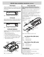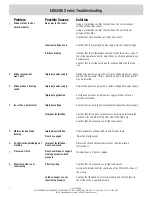
ES84/86 Series Installation Instructions
(Continued)
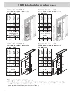
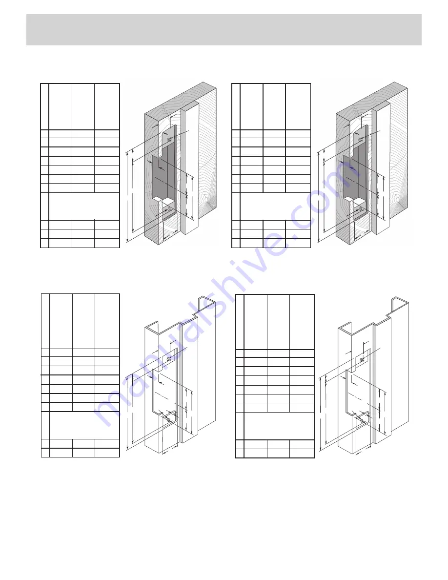
Hollow Metal Frames, 1-3/16” D
Modular ES86 FSV or ES86 FSV LKM or
ES86 U assembled with 86S4S faceplate
C
G
G
F
M
A
D
E
K
B
X
M
CL
CL
MEASUREMENT
FRACTIONA
l
INCHES
DECIMA
l
INCHES
METRIC
mm
A 1-1/4 1.250 31.75
b 4-7/8 4.875 123.83
C 3-3/8 3.375 85.73
D 1-3/16 1.188 30.16
E 3/8
.375 9.53
F
1/8*
.125* 3.18*
G 1-11/16 1.688 42.86
Vertical Vertical Vertical
X C/l
C/l
C/l
Door Door Door
K 4-1/8 4.125 104.78
M 12-24 —
—
Vertical Centerline
of Door**
Hollow Metal Frames, 1-1/16” D
Modular ES84 FSV or ES84 FSV LKM or
ES84 U assembled with 86S4S faceplate
C
G
G
F
M
A
D
E
K
B
X
M
CL
CL
MEASUREMENT
FRACTIONA
l
INCHES
DECIMA
l
INCHES
METRIC
mm
A 1-1/4 1.250 31.75
b 4-7/8 4.875 123.83
C 3-3/8 3.375 85.73
D 1-3/32 1.094 27.78
E 3/8
.375 9.53
F
1/8*
.125* 3.18*
G 1-11/16 1.688 42.86
Vertical Vertical Vertical
X C/l
C/l
C/l
Door Door Door
K 4-1/8 4.125 104.78
M 12-24 —
—
Vertical Centerline
of Door**
X
E
K
B
R
M
D
G
G
C
A
M
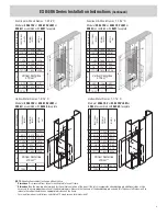
Aluminum & Wood Frames, 1-3/16” D
Modular ES86 FSV or ES86 FSV LKM or
ES86 U assembled with 86S7 faceplate
MEASUREMENT
FRACTIONA
l
INCHES
DECIMA
l
INCHES
METRIC
mm
A 1-7/16 1.438 36.51
b 7-15/16 7.938 201.61
C 3-3/8 3.375 85.73
D 1-3/16 1.188 30.16
E 1/4 0.250 6.35
F
1/8*
.125* 3.18*
G 1-11/16 1.688 42.86
Vertical Vertical Vertical
X C/l
C/l
C/l
Door Door Door
R 5/32 .156 3.97
K 7-7/16 7.438 188.91
M 12-24
†
— —
Vertical Centerline
of Door**
X
E
K
B
R
M
D
G
G
C
A
M
Aluminum & Wood Frames, 1-1/16” D
Modular ES84 FSV or ES84 FSV LKM or
ES84 U assembled with 86S7 faceplate
MEASUREMENT
FRACTIONA
l
INCHES
DECIMA
l
INCHES
METRIC
mm
A 1-7/16 1.438 36.51
b 7-15/16 7.938 201.61
C 3-3/8 3.375 85.73
D 1-3/32 1.094 27.78
E 1/4 0.250 6.35
F
1/8*
.125* 3.18*
G 1-11/16 1.688 42.86
Vertical Vertical Vertical
X C/l
C/l
C/l
Door Door Door
R 5/32 .156 3.97
K 7-7/16 7.438 188.91
M 12-24
†
— —
Vertical Centerline
of Door**
NOTE: Specifications subject to change without notice.
* Dimension F is measured from face of mounting tab to face of frame.
** Dimension X on the drawing is determined by the vertical centerline of the door. If the latch incorporates a deadlocking pin additional steps will be
necessary to ensure proper operation of the deadlocking pin. Measure the thickness of the deadlocking pin and add this thickness to Dimension X to
relocate the vertical centerline an appropriate distance on the frame.
†
For wood frame door installations, substitute #12 wood screws for dimension M.
3

