background image

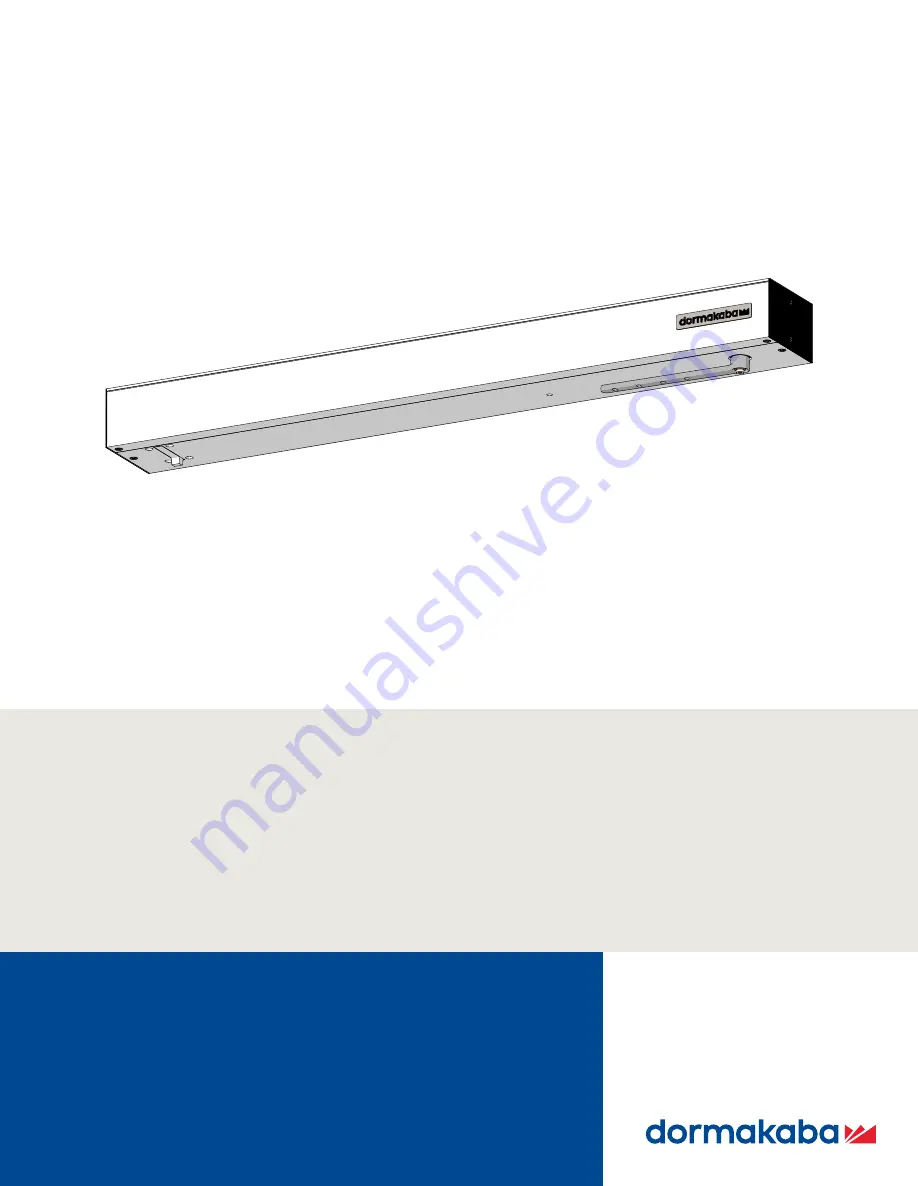
ED50/ED100/ED250 

Swing Door Operators  

Installation in Overhead Concealed Header

Door Installation, Setup,  

Troubleshooting and Maintenance 

Instructions

DL4617-003 – 09-2021

EN

 | 

Summary of Contents for 100

Page 1: ...ED50 ED100 ED250 Swing Door Operators Installation in Overhead Concealed Header Door Installation Setup Troubleshooting and Maintenance Instructions DL4617 003 09 2021 EN ...

Page 2: ...tomatic swing doors 21 9 9 Safety label low energy swing doors 21 Table of contents 10 Parameters 22 10 1 ED50 ED100 ED250 OHC viewing and changing parameters 22 10 2 Configuration parameters 22 10 3 Driving parameters 22 11 System setup for single door installation 24 11 1 Set operator spring tension 24 11 2 Set braking circuit plug position 25 11 3 ED50 ED100 ED250 OHC power on 26 11 4 Set insta...

Page 3: ...upgrade cards 49 21 Maintenance 50 21 1 ED50 ED100 ED250 environment and cleaning 50 21 3 Overhead arm and bottom door pivot 51 21 4 ED50 brake maintenance 52 Appendix A Driving parameters 54 A 1 Driving parameters detail 54 Appendix B Troubleshooting 64 B 1 Information and error codes 64 B 2 Red LED status codes 65 B 3 Troubleshooting chart ln codes 66 B 4 Troubleshooting chart E codes 67 Appendi...

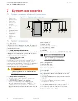
Page 4: ... force settings to counteract these conditions Door mounted presence sensors When attempting to overcome these forces it is strongly suggested that door mounted presence sensors be employed to enhance pedestrian safety through the opening 1 1 4 Manual storage This document must be kept in a secure place and accessible for reference as required If the door system should be transferred to another fa...

Page 5: ...A A156 19 Configured as a full energy operator ANSI BHMA A156 10 using parameter adjustment 2 3 3 ED250 Supplied as a low energy operator ANSI BHMA A156 19 Configured as a full energy operator ANSI BHMA A156 10 using parameter adjustment 2 4 ED50 ED100 ED250 separate modules Fig 2 4 2 4 1 Single door header modules supplied Low voltage wiring connection module Main power module 2 4 2 Pair door hea...

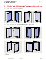
Page 6: ...D250OHCdoorconfigurations 3 1 OHC single door configurations Fig 3 1 1 LH inswing RH inswing Fig 3 1 2 LH outswing RH outswing Fig 3 2 4 RH double egress Fig 3 2 3 Inswing Fig 3 2 1 Outswing Fig 3 2 2 LH double egress 3 2 OHC pair door and double egress door configurations Jambs and doors supplied and installed by customer Locks optional ...

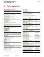
Page 7: ...ptimization Cycle counter CC parameter 0 to 1 000 000 Power assist function hA hF hS parameters Drive support for manual opening of door Push go function PG parameter Auto opening of door at 4 open 4 1 ED50 100 ED250 technical data 4 1 1 Required operating conditions Ambient temperature 5 to 122 F 15 to 50 C Suitable for dry rooms only Relative air humidity 93 maximum non condensing Power supply 1...

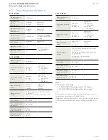
Page 8: ...vailing conditions at the door opening Door width 36 to 48 Door width for fire protection 36 to 48 Maximum opening speed s Note 2 FE 50 LE 27 Maximum closing speed s Note 2 FE 50 LE 27 Maximum power consumption 240 watts Automatic opening torque Minimum 20 N m 14 8 lbf ft Maximum FE 150 N m 110 6 lbf ft LE 67 Nm 49 4 lbf ft Automatic closing torque Minimum 20 N m 14 8 lbf ft Maximum FE 150 N m 110...

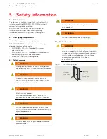
Page 9: ...ings WARNING Damage to equipment or incorrect equipment operation mayresult from an incorrect installation WARNING Hazard to mechanical processes by use of control settings elements or procedures not documented in this manual WARNING Electric shock hazard By use of control elements settings or procedures not documented in this manual WARNING Work on electrical equipment and 115 Vac wiring installa...

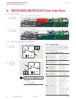
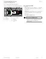
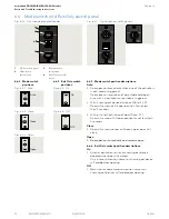
Page 10: ...value Downbutton 1 Scrollthroughparameters anderrormessages 2 Reduceparametervalue 3 Openingpulse press button 3s 4 Learningcycle press button 3s 5 Resetwithfactorysetting pressbutton 8s program switchCloseposition 6 Identifyoperator orientationfordisplay 2 2digitdisplay 6 Button legend rotated 180 6 2 1 4 button keypad 4 button legend is orientated so buttons have same function and position regar...

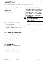
Page 11: ...tion system status or operating conditions or certain error codes E__ 2 Yellow LED Maintenance interval indicator When illuminated an indication the operator system has to be serviced 3 Green LED On internal 24 Vdc power is On Off internal 24 Vdc power is Off TIPS AND RECOMMENDATIONS Details on LED status codes and maintenance intervals can be found in Appendix B Troubleshooting 1 RedLED 2 Yellow ...

Page 12: ...r not less than 3 seconds Close 1 Door will remain closed or if door is open door will close Open 1 Door opens automatically and remains open 6 4 4 Exit Only switch position descriptions On 1 Exterior activation sensor or knowing act device disabled when door fully closed Only interior activation sensor or knowing act device will enable door opening Off 1 Both interior and exterior activation sens...

Page 13: ...tilizing the following design factors Reduced dynamic door panel contact forces Reduced static door panel contact forces Low driving speeds Force limitation 6 6 1 2 Knowing act definition Any conscious action with the expected result of opening a door This includes but is not limited to Wall or jamb mounted contact or non contact switches such as pushplates The action of of manually opening pushin...

Page 14: ... This supply has overcurrent protection If additional power is required an external power supply must be used 7 2 System accessories 1 External mode switch mechanical 2 Externalmode switch electronic 3 Keyswitch 4 Pushbutton night bank 5 Pushbutton interior 6 Pushbutton exterior 7 Door locking device 8 Manual release switch 9 ED50 ED100 ED250 7 2 6 Activators Typical activators 1 Pushbuttons key s...

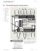
Page 15: ...pter 12 97 98 99 30 31 32 34 33 3 3 35 1 3 6 1 4 4a 3 B A 1 57 57a 1 42 3 1 41 3 1 15 17 3 1 11 13 3 43 3 64 63 62 1G 3 24 V Signal input 0 V Partial Open Permanent Open Exit Only Automatic Off N C COM Test output X5 X4 X3 X6 X9 X1 X7 24 V X8 0 V X10 8 24 AC DC 5 Wet DCW bus Safety sensors Activation inputs Interior Exterior Night bank input 24 V Signal input 0 V 24 V 24 V Signal input Signal inpu...

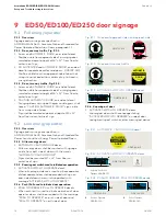
Page 16: ... 010 AUTOMATIC DOOR DO NOT ENTER CAUTION DOOR AUTOMATIC DD0756 010 dormakaba 9 2 Low energy operator 9 2 1 Overview Signage and warnings are specified in ANSI BHMA A156 19 American National Standard for Power Assist and Low Energy Power Operated Doors 9 2 2 All low energy doors 1 AUTOMATIC CAUTION DOOR decal All low energy doors shall be marked with signage visible from both side of door with the ...

Page 17: ...raffic Approach side Swing side Approach side Swing side DD0739 010 AUTOMATIC DOOR DO NOT ENTER 50 12 AUTOMATIC DOOR CAUTION DOOR AUTOMATIC DD0756 010 dormakaba 50 12 AUTOMATIC DOOR 50 12 CAUTION DOOR AUTOMATIC DD0586 010 DD0758 010 ACTIVATE SWITCH TO OPERATE DD0758 010 DD0758 010 ACTIVATE SWITCH TO OPERATE DD0758 010 CAUTION DOOR AUTOMATIC DD0586 010 DD0758 010 ACTIVATE SWITCH TO OPERATE DD0758 0...

Page 18: ...nowing act approach side one way 50 12 AUTOMATIC DOOR AUTOMATIC DOOR 50 12 AUTOMATIC DOOR AUTOMATIC DOOR 50 12 AUTOMATIC DOOR AUTOMATIC DOOR DD0758 010 ACTIVATE SWITCH TO OPERATE DD0758 010 DD0758 010 ACTIVATE SWITCH TO OPERATE DD0758 010 DD0758 010 ACTIVATE SWITCH TO OPERATE DD0758 010 DD0758 010 ACTIVATE SWITCH TO OPERATE DD0758 010 50 12 DD0739 010 AUTOMATIC DOOR DO NOT ENTER DD0739 010 AUTOMAT...

Page 19: ... 9 6 4 Push pull door pull swing side Fig 9 6 2 Push pull door push approach side 50 12 CAUTION DOOR AUTOMATIC DD0586 010 CAUTION DOOR AUTOMATIC DD0586 010 DD0758 010 ACTIVATE SWITCH TO OPERATE DD0758 010 DD0758 010 ACTIVATE SWITCH TO OPERATE DD0758 010 DD0758 010 ACTIVATE SWITCH TO OPERATE DD0758 010 DD0758 010 ACTIVATE SWITCH TO OPERATE DD0758 010 50 12 CAUTION DOOR AUTOMATIC DD0586 010 CAUTION ...

Page 20: ...Approach side Swing side Fig 9 7 6 LH double egress exterior side Fig 9 7 5 LH double egress Fig 9 7 1 OHC RH double egress Fig 9 7 4 OHC LH double egress Swing side Approach side 50 12 DD0739 010 AUTOMATIC DOOR DO NOT ENTER AUTOMATIC DOOR 50 12 DD0739 010 AUTOMATIC DOOR DO NOT ENTER AUTOMATIC DOOR Approach side Swing side 50 12 DD0739 010 AUTOMATIC DOOR DO NOT ENTER AUTOMATIC DOOR 50 12 DD0739 01...

Page 21: ...on label SAFETY INFORMATION Low Energy Swinging Doors 1 Activate the door Door shouldopen at a slow smooth pace 4 or more seconds and stop without impact 2 Doormustremainfullyopen foraminimumof5seconds before beginning to close 3 Doorshouldcloseataslow smooth pace 4 or more seconds and stop without impact 4 Inspect the floor area It should be clean with no loose parts that might cause user to trip...

Page 22: ...displayed Step 8 Press left button for a minimum of 3 s to exit program mode 10 3 1 Driving parameters Driving parameters Table 10 3 1 can be set once initial setup Chapter 10 has been completed Reference Appendix A for driving parameter detail 10 1 1 Changing parameter values 1 Set Mode switch to the CLOSE position Fig 10 1 1 Mode switch Fig 10 1 2 4 button keypad 2 digit display 2 2 digit displa...

Page 23: ...26 du Door unlocking during business hours 27 Sr Status relay function terminal block X7 28 bE Input 4 4a and X3 1G 24V locking device output configuration 29 CC Cycle counter number displayed 10000 30 EC Delete error log Driving parameter Description 31 CS Reset service interval display yellow LED 32 SL Factory setting level Fact Setup button 33 OA Opening angle set during learning cycle 34 hd Do...

Page 24: ...set fully CCW no spring tension CAUTION A minimum of ten spring tension revolutions are required to operate system Fig 11 1 1 Spring tension adjustment example 1 OHC header 2 ED50 ED100 ED250 operator 3 Header access hole spring tension adjustment 4 T handle hex key 5 mm 2 3 4 1 11 System setup for single door installation 11 1 4 Set operator spring tension 1 Set operator spring tension revolution...

Page 25: ... outswing or inswing installation WARNING Braking circuit will not work correctly if braking circuit plug is improperly positioned or if an incorrect plug is used Door may close at high speed and or be difficult to open 11 2 2 Braking circuit plug outswing position Braking circuit plug is factory installed in the two pins away from user interface the outswing position Fig 11 2 2 11 2 3 Changing br...

Page 26: ...ove up and down 7 letters and numbers will change if required to display correct orientation 2 Display scrolls 8 Device ID Ed 250 as example Firmware version format F x x x x 3 Program mode display Program mode 9 will be displayed indicating system requires further parameter settings TIPS AND RECOMMENDATIONS If pressing down button Para 11 3 3 does not result in desired display orientation return ...

Page 27: ...1 5 set door width parameter Tb 11 4 1 Set AS OHC parameter value Installation type Parameter value Parameter description 0 Pull arm with track wall mounting on swing hinge side 1 Push arm wall mounting on approach opposite hinge side 2 Push arm with track wall mounting on approach opposite hinge side 3 Overhead concealed OHC RH 4 Overhead concealed OHC LH 5 ED250 only ANSI 6 door width 55 Table 1...

Page 28: ... 3 must be followed 2 Set TB parameter to value other than 10 Follow steps in Para 11 5 4 Step 8 Press Scroll to Tb parameter Step 9 Press Displays 10 factorysetting Step 10 Press 10 starts flashing Step 11 Press Scroll to 11 Door width 44 47 15 16 as example Step 12 Press Saves value entered Display stops flashing Step 13 Press Returns to door width parameter Step 14 Go to Para 11 6 Set reveal de...

Page 29: ...Step 17 Press 00 starts flashing Step 18 Press Scroll to 01 Step 19 Press Scroll to 00 Step 20 Press Saves value Display stops flashing Step 21 Press Returns to reveal depth parameter Step 21 Go to Para 11 7 Set door type parameter dL 11 6 2 Set parameter rd reveal depth 0 Fig 11 6 1 Reveal depth parameter rd 11 6 1 Set rd reveal depth parameter value to 0 NOTICE 1 OHC reveal depth 0 set rd 0 0 is...

Page 30: ...Active door operator door opens first 2 Pair doors with astragal Inactive door operator 3 Pair doors without astragal Active door operator Both doors open simultaneously 4 Pair doors without astragal Inactive door operator Both doors open simultaneously Table 11 7 1 Door type parameter dL values dL factory setting 0 11 7 2 Set dL door type parameter value NOTICE 1 Set dL 0 single door 0 0 is dL fa...

Page 31: ...tes to find door closed position See Step 1 Arm must be blocked so arm cannot travel past the door closed position Arm performs several movements and display shows a sequence of symbols Movements of arm must not be interrupted Display indicates arm is at 70 position Reference Fig 11 8 4 Step 4 If desired manually move door to 900 position for door installation TIPS AND RECOMMENDATIONS Arm must be ...

Page 32: ...11 Fig 11 8 3 Overhead arm at zero degree closed position Fig 11 8 4 Overhead arm at 70 degree position for door installation LH inswing example Fig 11 8 5 LH outswing Fig 11 8 6 RH outswing Header cover Header cover Header cover Fig 11 8 7 LH inswing Header cover Fig 11 8 8 RH inswing 11 8 3 Door overhead arm configurations ...

Page 33: ...tion must meet ANSI BHMA standards as well as any applicable local building codes 12 1 1 Conditions prior to installing door 1 Overhead arm rotated to 700 open position or greater Fig 11 8 4 2 Floor pivot installed by customer 3 Door bottom pivot hardware installed in floor by customer CAUTION Jamb edge to floor pivot centerline distance 3 3 4 Reference Para 12 3 12 1 2 Check ED operator to floor ...

Page 34: ...arm using dimensions referenced in Fig 12 2 2 and 12 2 3 2 Drill four holes for selected 1 4 hex head bolts Fig 12 2 2 Door mortise for overhead center hung arm LH inswing or RH outswing example 3 819 1 73 1 73 1 73 2 X Ø 38 2 X 281 50 53 75 10 62 269 7 R 38 32 Ø 1 25 63 4 45 34 10 1 3 8 34 10 Door mortise for arm 6 7 16 1 3 8 1 3 4 1 3 4 1 3 4 C L Arm installed in door reference view A A A No sca...

Page 35: ...Mortise bottom of door for bottom door pivot using dimensions referenced in Fig 12 3 2 and 12 3 3 2 Drill holes for selected 1 4 fasteners in the two slotted holes 12 3 2 Install bottom door pivot 1 Place bottom door pivot in mortise 2 Install fasteners and tighten 1 1 Door pivot release lever 12 4 Install floor pivot shaft bearing Fig 12 4 1 Floor pivot and bearing 1 Floor pivot 6 Bearing 12 4 1 ...

Page 36: ...head arm 1 Hold door vertical and parallel to overhead arm 2 Move door under overhead arm Fig 12 5 2 12 5 3 Slide door onto bottom pivot 1 Slide bottom door pivot release lever over bottom pivot Fig 12 5 1 until door lowers onto bottom pivot bearing Fig 12 5 4 Bottom door pivot release lever holds door bottom pivot in place over bearing 2 Overhead arm mounting holes should be aligned with hex bolt...

Page 37: ...ig 12 5 6 2 Tighten four overhead arm hex bolts Fig 12 5 7 12 5 6 Check door plumb and level 1 Check door plumb and level Adjustment can be made by loosening fasteners in floor pivot slotted holes Para 12 3 and adjusting floor pivot as required 4 3 4 1 1 2 3 Overhead arm 4 Door mortise 4 1 Clearance hole for hex bolts Bottom of door mortise Fig 12 5 6 Door mortise surface in contact with arm Fig 1...

Page 38: ...nts of door must not be interrupted Display indicates door is at 70 position and is waiting for door opening angle to be set Step 4 Manually move door to desired opening angle Maximum door angle is 110 Step 5 Press Momentarily press down button to continue learning cycle Door performs several movements and display shows a sequence of symbols Movements of door must not be interrupted Door completes...

Page 39: ...blade screwdriver required for adjustment 13 1 2 Setting door closing speed upon power failure 1 Turn ED50 ED100 ED250 power switch OFF 2 Manually open door to 90 angle and let it close 3 If door closes in less than 3 seconds turn potentiometer 1 4 turn CW and retry test Repeat as necessary TIPS AND RECOMMENDATIONS Total door closing time from full open to fully closed should not be less than 5 se...

Page 40: ...11 performed for each ED operator 2 Overhead arms rotated to 700 open position or greater 14 1 2 Floor pivots installed by customer 1 Floor pivots installed by customer CAUTION Jamb edge to floor pivot centerline distance 3 3 4 Reference Paa 12 3 2 Bottom pivot hardware installed in floor by customer for both doors 14 1 3 Check ED operator axle to floor pivot plumb NOTICE Using plumb bob check ED ...

Page 41: ...r without astragal Passive door operator Both doors open simultaneously Factory setting Step 1 Press Press and hold right button greater than 3 seconds to enter program mode AS parameter displayed Step 2 Press Scroll to dL parameter Step 3 Press Displays 00 factorysetting Step 4 Press 00 starts flashing Step 5 Press Scroll to select parameter value 1 as an example Step 6 Press Saves value entered ...

Page 42: ...cable to active and passive operator RJ45 horizontal jacks 4 Secure cable inside header 15 2 2 Test door operation 1 Set Mode switch to AUTO 2 Test double door operation TIPS AND RECOMMENDATIONS In sensors have not been connected set Mode switch to OPEN and after doors have opened set back to CLOSE Fig 15 2 2 Sync cable jack 1 ED50 ED100 ED250 operator RJ45 jack horizontal for Sync cable 2 Sync ca...

Page 43: ...ce Chapter 8 Terminal Board Connections for terminal board interfaces Reference ED100 ED250 Sensor Installation and Wiring Manual 1 Terminate all accessory wiring for both LH and RH doors at ED50 ED100 ED250 low voltage terminal board modules in header 2 Secure all accessory wiring in header 17 2 2 Panic breakout switch wiring Reference Para 17 1 2 17 2 3 Test system accessories Test functionality...

Page 44: ...tion Install applicable door signage as outlined in Chapter 9 ED50 ED100 ED250 door signage 18 2 Install header cover 18 2 1 Install header cover CAUTION 1 Insure all wiring is secured inside of header 2 Check tightness of all wiring connections 3 Check ribbon cable connections Fig 18 2 1 Single door header cover 1 1 4 20 x 1 2 FHMS 1 Fig 18 2 2 Header cover fastener 1 Secure header cover to jamb ...

Page 45: ...0s 0s 180s F2 2 10 2 4 Shallremainopenaminimumof1 5seconds afterlossofdetection Latch check Checkingorslowingdownof doorspeedbeforedoorbeing fullyclosed Notadjustable 10 2 6 Shalloccurforaswingingdooratnolessthan 10 fromclosedposition Thedoorwillnotclosethroughthefinal10 in lessthan1 5s hS Reference AppendixBfor parameter detail Supportformanualmodein doorclosedposition 10 2 8 Manualopeningforcein...

Page 46: ...notless than5s Exception whenpush pullactivationisused thedoorshallremainatthefullyopened positionfornotlessthan3s hS Reference AppendixAfor parameter detail Supportformanualmodein doorclosedposition 4 6 Reference ANSI BHMA A156 19 Para 4 6 Force and Kinetic Energy hA Adjustment dooractivation angle hF Powerassistfunction Fo Static force in opening direction Staticforceondoorclosing edgeinopeningd...

Page 47: ...ng time from 90 degrees to latchcheck or 10 degrees whichever occurs first 19 2 2 A156 19 Table I Minimum opening and closing times 19 2 3 A156 19 Table II Total opening time to 90 degrees Backcheckat60 Backcheckat70 Backcheckat80 TableIplus2s TableIplus1 5s TableIplus1s Ifdooropensmorethan90 itshallcontinueatthesamerateasbackcheckspeed Backcheckoccurringatapointbetweenpositionsshalluselowestsetti...

Page 48: ...led functions will be deactivated after a certain time 20 2 3 Operator control unit replacement If the control unit is replaced the container module is removed from the old control unit and inserted into the new control unit The new control unit synchronizes with the container module and all upgrade card functions are available 20 2 4 Inserting an upgrade card that has already been activated Rapid...

Page 49: ...ble parameter F1 F8 for card Reference Chapter 10 Parameters 1 Remove container module from upgrade card slot 6 1 2 Insert next upgrade card into upgrade card slot 4 6 Card function is copied to control module upgrade card is then invalidated Yellow LED indicates procedure is complete 6 1 3 Remove upgrade card from upgrade card slot 4 Reinsert container module into upgrade card slot Control unit r...

Page 50: ...e external header surfaces 21 1 4 Water and other liquids CAUTION No water or other liquids must be sprayed or spilled on ED50 ED100 ED250 OHC header Table 21 1 1 Operator environmental requirements Fig 21 1 1 ED50 ED100 ED250 OHC header and LH door Ambient temperature 5 to 122 F 21 2 Operator status LEDs maintenance interval Fig 21 2 1 Operator status LEDs 21 2 1 Operator status LEDs maintenance ...

Page 51: ...ction to drive axle 1 Remove door s Door s must be removed to check overhead arm connection to drive axle and bottom door pivot Reference Chapter 12 single door or Chapter 14 double door for door installation 2 Check arm and extension hardware for wear and tear 3 Check tightness of M8 SHCS CAUTION Use Torque wrench with 5 mm hex key socket to tighten M8 screw to 17 ft lb 23 Nm 21 3 2 Check bottom ...

Page 52: ...tenance CAUTION Air gap setting between brake and brake disc 0 1 mm to 0 3 mm 0 004 to 0 012 1 Using 2 5 mm hex key loosen three M3 x 3 set screws securing brake disc to motor shaft 2 Insert feeler gauge air gap setting for sizing between brake disc and brake 3 Move brake disc against shim s 4 Screw M3 x 3 set screws against motor shaft but do not tighten 5 Remove feeler gauge 6 Tighten M3 x 3 set...

Page 53: ...4 6 Brake disc assembly removed from brake 2 5 1 1 Brake assembly 2 Brake disc assembly 5 Motor shaft 1 2 6 6 Fig 21 4 5 M3 x 5 SHCS 1 Brake assembly 2 Brake disc assembly 6 M3 x 5 SHCS 21 4 2 Torque setting of M3 x 5 SHCS 5 3 in lb 0 9 in lb 0 6 Nm 0 1 Nm 2 6 6 1 1 Brake assembly 2 Brake disc assembly 6 M3 x 5 SHCS Fig 21 4 8 Brake coil wiring 43 3 64 63 62 1G 3 1G Red 3 Blk ...

Page 54: ...e closing speed range ED100 ED250 Full adjustable range of closing speeds available only when configured for full energy Parameter F2 Maximum closing speed reduced to 27 s in low energy mode 1 After adjustment internal monitoring system checks if parameter setting is admissible If setting exceeds admissible value the setting is alternately displayed with the permissible value 2 After adjustment In...

Page 55: ...nal To insure personnel safety it is advised to keep this range as small as possible If set wall masking angle is exceeded when door is being opened a rapidly flashing dot appears in top left hand corner of 2 digit display Rapidly flashing dot disappears when door angle drops below set wall masking angle 10 60 99 80 Safety sensor test 11 0 8 0 Safety sensor parameter ST must be set to sensors used...

Page 56: ...eter Ud delayed opening time for locking mechanism To maintain long service life set preload force only as high as necessary 15 0 9 0 Power reserve module SVP PR 12 test 16 0 1 0 0 Test off 1 1 SVP PR 12 power reserve module test is performed once every 24 hours or 10 minutes after AC power has been turned on In event of an error Unlocking is not performed and no automatic door movements are initi...

Page 57: ...er setting is designed to increase static force on door closing edge to insure proper closing despite resistance caused by door seals or locking devices 1 After EP parameter set verify setting meets ANSI BHMA standards See Chapter 19 After parameter adjustment internal monitoring system checks if parameter setting is admissible If setting exceeds admissible value the setting is alternately display...

Page 58: ...when power returns Important The time at which power returns might not be during business hours and may affect insurance compliant door locking requirements 1 In event of power failure or if operator is deliberately switched off EPS will automatically switched to OFF position when power returns This function should be used iif insurance compliant locking if required Internal program switches switc...

Page 59: ...ng device output terminal X3 1G 24V is independent of Input X6 4 4a 1 Locking device output terminal X3 1G 24V is turned on as soon as contact at X6 4 4a is opened Terminal X3 1G 24V output is on for as long as contact at X6 4 4a is open motor lock with a 100 duty factor is required This function is not available for DCW motor locks Cycle counter Total number of opening and closing cycles displaye...

Page 60: ...ing cycle is displayed Opening angle can only be changed during learning cycle Due to installation and parameter tolerances display value may not match actual door position 33 0 110 Door closer mode 34 0 1 1 0 0 Automatic mode This mode is applicable whenever door is mainly opened automatically and where motion detectors are installed Mode is optimized for high frequency use Full energy upgrade ca...

Page 61: ...lable 1 Upgrade card installed function not activated 2 Upgrade card installed function activated 3 Upgrade card has been removed function no longer available Upgrade card fire protection 1 Activate function by installing upgrade card parameter value will automatically change to 2 upgrade card function installed fire protection function activated Following activation drive may be used as a electri...

Page 62: ...terface 45 0 1 0 0 Interface programmed for communication with dormakaba handheld 1 Interface programmed for use with dormakaba TMS Soft control software Backcheck when door opened manually Angle after which door is braked when manually opened Back check level is automatically optimized during manual door opening cycles bc function improves door braking behavior in end position so door does not mo...

Page 63: ...for the calculated door angle HS parameter may only have a small effect but the hinge clearance can be adjusted in extreme cases to improve accuracy Factory setting is 3 10 30 mm 1 3 16 With CPD doors setting must be changed to a negative value A learning cycle is then required as system creates an angle table as a function of the set parameters 52 5 10 mm 3 10 3 16 10 inches Overhead concealed mo...

Page 64: ...e Users can then access door manually B 1 3 User information display User interface display or or dormakaba handheld displays Information ln codes Error message E codes B 1 4 Viewing error messages To access and view error messages briefly press the right button on the 4 button keypad B 1 5 Red LED on operator Red LED adjacent to operator power switch displays blinking codes for Certain ln informa...

Page 65: ...tiblefireprotection setting Flashing 7 times E71 Systemerror1 test second shutdownoption Flashing 7 times E72 Systemerror2 test current measuringcircuit Flashing 7 times E73 Systemerror3 test brakingcircuit Flashing 12 times E12 EEPROMerror Flashing 13 times E13 Motorovercurrent Flashing 15 times E15 Faultylearningcycle B 2 1 Red LED status codes B 1 7 Error message memory 1 There are ten error me...

Page 66: ...rd installed first container module has not been reinstalled or is defective 1 Installed upgrade card cannot be removed If more than one upgrade card is installed the first card installed becomes the container module The container module must be installed last after all other Upgrade cards are installed 2 If container module is defective first upgrade card container module must be replaced and all...

Page 67: ...be displayed 9 ln 91 Off DCW communication At least one registered DCW device is missing 1 Reconnect the corresponding DCW device 2 If this is not possible reactivate the drive Reactivation can be done by Switching program switch to Close off Pressing both 4 button keypad left and right buttons greater than 3s B 3 1 Troubleshooting chart information messages No Display Red LED Description Troubles...

Page 68: ...eserve module test Check power reserve module and its wiring 8 E 26 Brake error Reference Chapter 21 Maintenance Para 21 4 Brake maintenance 1 Brake error during learning cycle Check brake wire connections on X3 terminal strip Verify wire insulation has been properly stripped from end of wires and wires are secured under terminals Red wire terminated on 1G black wire on 3 Reference Figure 21 4 8 b...

Page 69: ...nction test always results in the error code the control unit must be replaced 14 E 73 Flashing 7 x System error 3 braking circuit The braking circuit is a safety element in the closer mode and will be tested every 24 hours During the test the motor is shut down during door closing and the door closes at a set angle in emergency mode Test can be noticed as a short jerk on the door and is normal Er...

Page 70: ...amage to operator C 1 2 Handheld key functions 1 OFF ON switches Handheld on or off 2 Function keys F1 F3 trigger functions shown in bottom line of display e g RPT for repeat UP and DOWN to switch lines UpDoLd for file up and download CHANGE to change values OPEN to trigger opening pulses 3 Arrow keys allow navigation within the display Use left arrow to get back to previous screen 4 ENTER selects...

Page 71: ... Language Selection menu 6 Press F3 to select Änd Amendments 7 Scroll down SPRACHEN menu to Englisch Press once to highlight Englisch 8 Press ENTER to select Englisch Fig C 2 1 dormakaba handheld Fig C 2 9 Englisch highlighted Fig C 2 10 SETTINGS menu TIPS AND RECOMMENDATIONS Handheld programmer will retain English setting when unit is turned off Change to English only required the first time the ...

Page 72: ...1 port Para 27 1 and power on Handheld will boot up and display main menu C 3 1 Firmware update procedure CAUTION For all firmware changes set program switch to CLOSE and allow door to close completely before any updates are made 2 With Communication highlighted press ENTER 3 Enter handheld user code and press ENTER MAIN MENU Files User code Communication MAIN MENU Files User code Communication Se...

Page 73: ...ss ENTER Fig C 3 7 Start transmission 7 Press any key to start firmware transmission DOWN UPLOAD Upload file Download data Firmware upload Door Connected with FW Version 02 30 Revision 000 ED100_US Again UpDoLd Door Connected with FW Version 02 30 Revision 000 ED100_US Again UpDoLd Door Operator Vers Rev Top Down ED100_US V02 20 000 ED100_US V02 00 000 ED100_US V02 30 000 Fig C 3 8 Firmware upload...

Page 74: ...www dormakaba us dormakaba USA Inc 1 Dorma Drive Drawer AC Reamstown PA 17567 USA T 717 336 3881 F 717 336 2106 ...

Reviews: