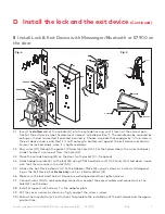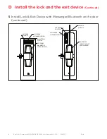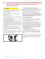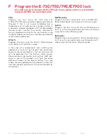
4
Exit Device Operators 630/750/79E/RT/E7900 Series/ Generation E-730 PK3677_T
10-18
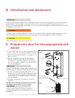
1) Choose from the DT kit the drilling template of the
lock for the exit device to be assembled on the door.
2) Mark the desired handle height on the edge of the
door. (see Fig.1)
3) Mark the backset vertical line on each side of
the door. Consult the exit device manufacturer’s
instructions for the correct backset. The backset
shown on the paper template is for reference only.
use exit device backset.
CAUTION
WARNING
IMPORTANT
Respect all applicable building codes regarding the
handle height of the lock and positioning of the bar.
4) Position the drilling template (attached in this
booklet) on the inside of the door aligning the door
handle height mark and backset vertical line mark
with the lines on the template. Mark the door for
the holes position.
5) Drill holes to diameters specified on the drilling
templates.
Drill the holes in the door required for the exit device
according to the manufacturer’s instructions.
CAUTION
WARNING
IMPORTANT
Drill from both sides of the door to prevent
unsightly damage. Refer to template for drill size
and depths
3 through holes
From the inside, counter bore
5/16 dia. X 3/4 deep
See Drilling Template
2 or 4 Holes
Backset Vertical Line
Inside of Door
3
4
Fig. 1
Fig. 2
B Introduction and disclaimers
C Prepare the door for the appropriate exit
device
CAUTION
WARNING
IMPORTANT
Please read and follow all directions carefully. These instructions are designed for use by maintenance
professionals or lock installers who are familiar with common safety practices and competent to
perform the steps described. dormakaba. is not responsible for damage or malfunction due to incorrect
installation, that may arise.
CAUTION
WARNING
IMPORTANT
Carefully inspect windows, doorframe, door, etc. to ensure that the recommended procedures will not
cause damage. dormakaba standard warranty does not cover damages caused by installation.
CAUTION
WARNING
IMPORTANT
Wear safety glasses when making the holes.


