System description
Technical Manual
16
V28 - 08/2019
Electronic safe lock
•
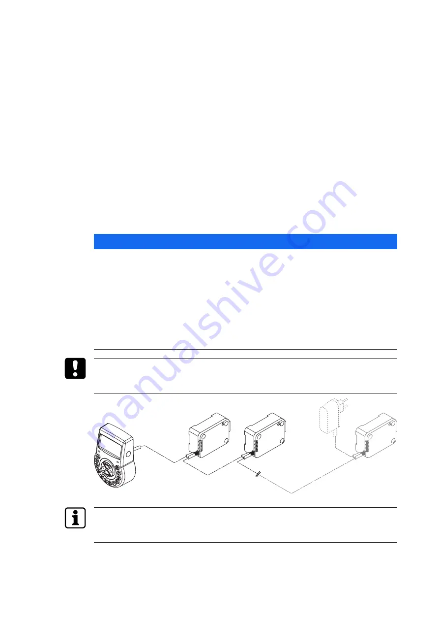
Connecting cable
The lock provides:
•
2 inputs
•
2 outputs
A further option is to connect an external power supply (6V DC/500mA) to the connection
sockets X1 or X2.
Requirements:
•
Only use the original Axessor power supply, 6 VDC, 2 A.
•
Only use non-rechargeable AA alkaline or AA lithium batteries.
•
Batteries must always remain in the battery compartment, even if the external power
supply is connected as they serve as energy source in case of power failure.
6.2.2
Standalone variant with multiple locks
NOTICE
Battery discharge and heating up
Operating a safe lock system with 2 input units being powered with batteries will cause a bat-
tery discharge due to potential equalization.
The battery discharge is faster than in normal conditions and requires an earlier replacement
of batteries.
Batteries can heat up due to potential equalization.
•
Only put batteries in the battery compartment of 1 input unit of a safe lock system.
•
Use external power supplies for a safe lock system to support the batteries of the single
equipped input unit with additional energy.
Not more than 10 locks to be connected in a safe lock system.
Not more than 4 bolts to be moved at a time. There is a high risk that a motion fault can be
caused.
1
2
3
4
5
6
7
8
1
2
3
4
5
6
7
8
1
2
3
4
5
6
7
8
10.
1.
2.
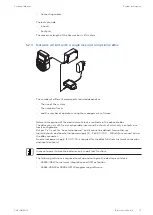
It is highly recommended to place the additional external power supply in the last position of
the safe lock system. In that way the units will be powered from both sides of the Axessor
bus.
The standalone variant with multiple locks is battery powered consisting of:
•
Up to 2 input units
•
Up to 10 locks


