Installation
Technical Manual
58
V28 - 08/2019
Electronic safe lock
40
41.3
55
10
4 x M4
1
3
2
6
10
6
5
4
193
90
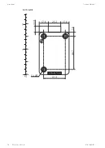
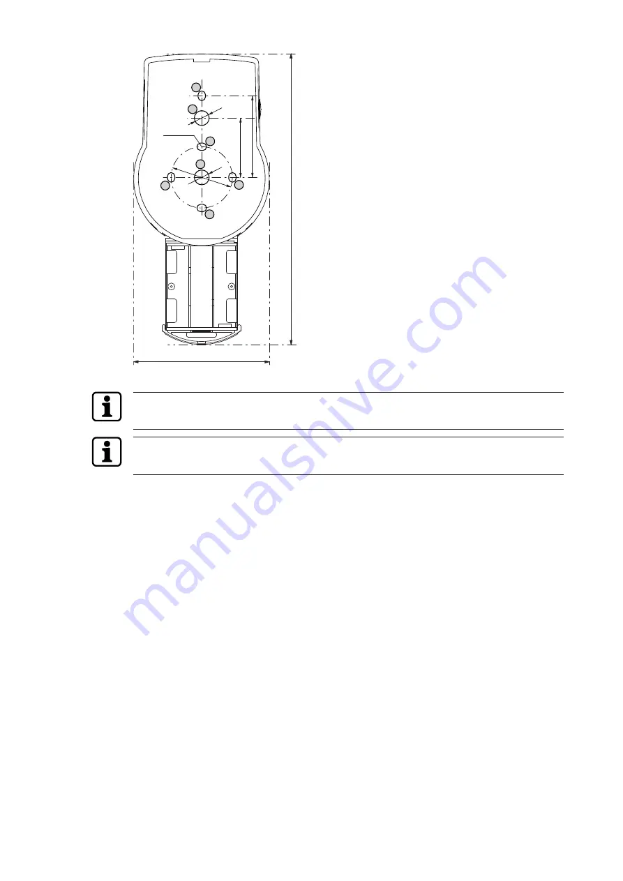
Installing the base plate
If the lock is installed directly behind the spindle hole and no other measure was chosen, a drill
protection plate is required for UL approved retrofit installation.
Fastening screws must be secured against loosening, e.g. by using threadlocking adhesive
such as Loctite 243 (medium strength, blue).
1.
Use the drilling template.
2.
Mark either fixation holes 3 and 5 or 2 and 4 plus fixation hole 1 .
3.
Also mark the fixation hole 6 for the cable feed-through.
4.
Drill 3 fixation holes Ø3.2x14 mm.
5.
Drill 1 hole Ø10 mm for the cable feed-through.
6.
Remove burrs.


