Installation
Technical Manual
65
V28 - 08/2019
Electronic safe lock
1
2
3
4
5
6
7
8
m
a
x
.
1
0
0
0
N
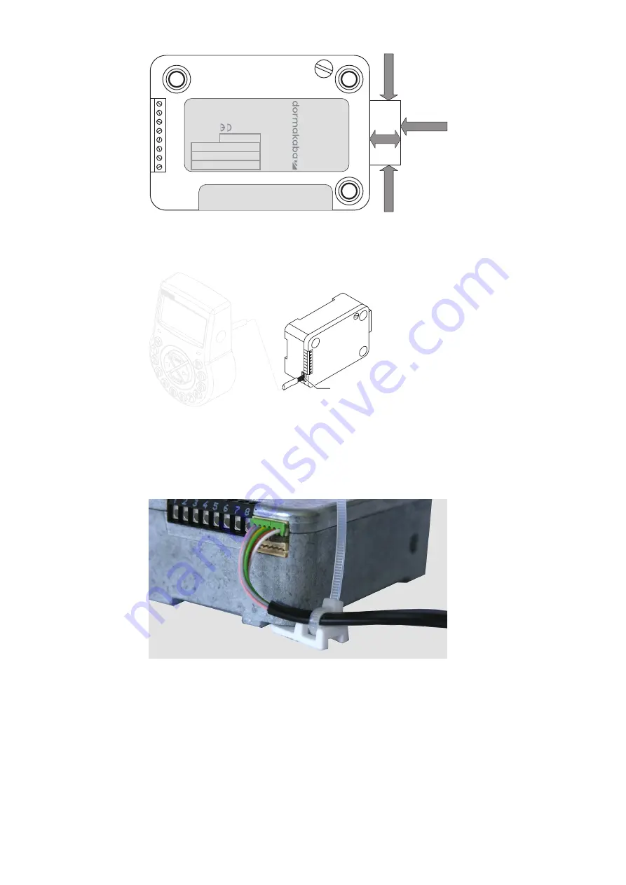
max. 5N
m
a
x
.
1
0
0
0
N
max. 1000N
Typ
e
Part N
o.
Serial
N
o.
Versi
on
Ce
rts.
AXESSOR
XXXXXXXXXX
XXXXX.XXXXXX/XXX
xxxx
x.x
x
20
17
Connecting the connecting cable
1
2
3
4
5
6
7
8
X1, X2
1.
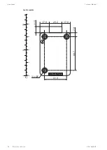
Make sure that the connector is in the correct position.
2.
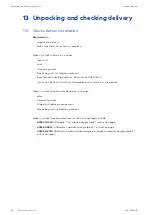
Carefully plug the connecting cable into 1 of the lock sockets X1 or X2.
3.
Tighten the connecting cable with the cable tie and carefully attach excess cable.
14.4
External connections on the lock
The configuration of input 2 and the corresponding terminals 7 and 8 is realized via AS284-
USB or AS284-NETW programming software.
Input 2 operates with inverted logic.
When input 2 is assigned as "door contact" and the checkbox "invert contact (open contact
to trigger)" is not selected in AS284-USBW or AS284-NETW programming software, the lock
evaluates the open lock terminals 7 and 8 being electrically disconnected as "door open".
Once the lock is open, the bolt remains as long open as the terminals 7 and 8 are open.


