A89995_A
©
2019 All rights reserved.
3/8
BEST is a trademark of dormakaba USA Inc.
1
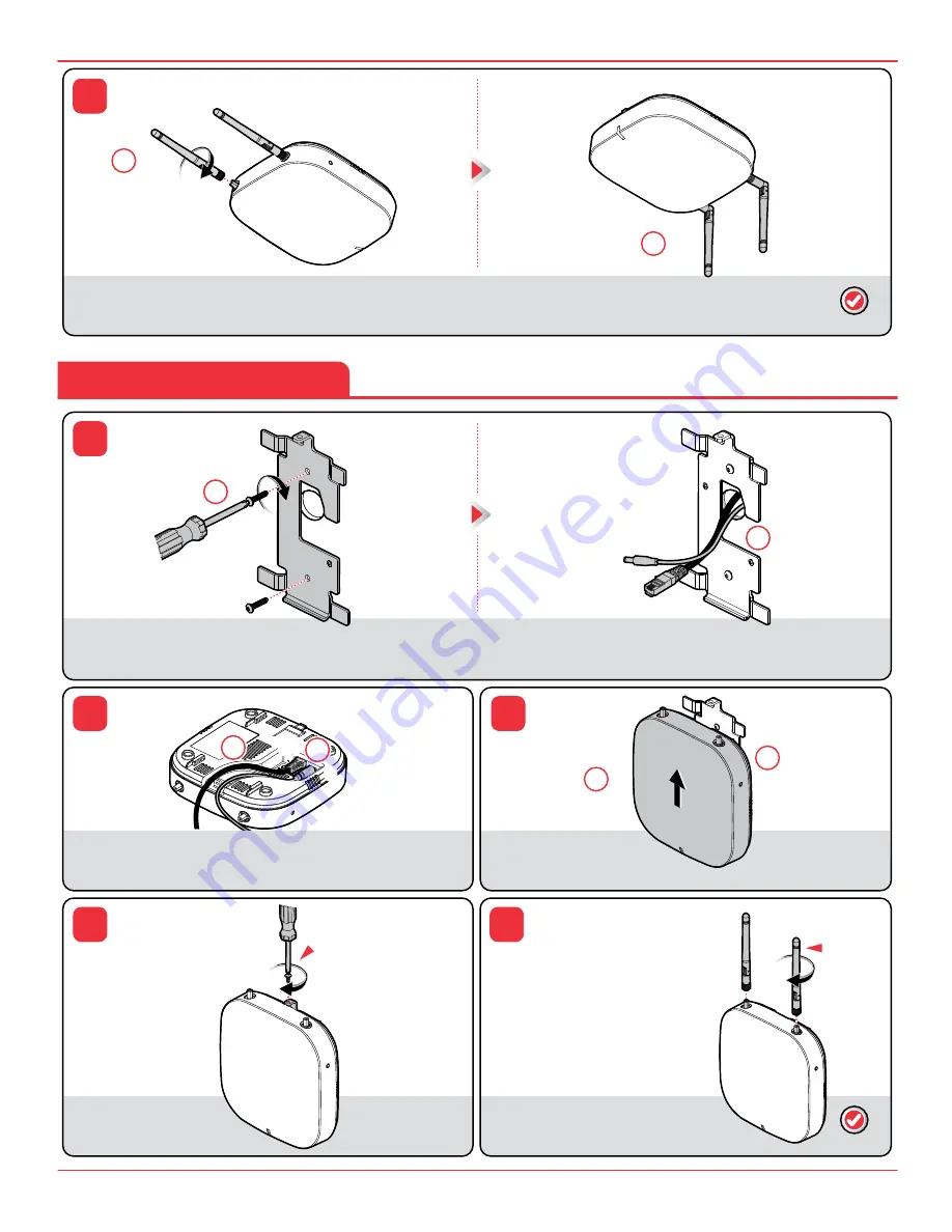
Attach the mounting bracket assembly
(C)
to the wall using the appropriate anchors
and screws.
2
If the Ethernet cable
(H)
and the DC power cable
(G)
will be pulled through the wall surface, both cables
must exit the wall in the area shown.
Install the #6-19 x 1/4"
retaining screw
(F)
.
Install the antennas
(B
(2x)
)
onto the gateway
(A)
using 4-6 in-lb torque. The antennas
(B
(2x)
)
must be oriented vertically when installed.
1
2
3
4
5
1
Slide the gateway
(A)
onto the
mounting bracket assembly feet
(C)
until it snaps into place.
2
Push any excess cable
back into the wall.
2
ATTACH MOUNTING
BRACKET ASSEMBLY
CONNECT
CABLES
SLIDE/SNAP
ON GATEWAY
INSTALL
RETAINING
SCREW
INSTALL
ANTENNAS
ROUTE
CABLES
F
C
H
G
H
A
A
A
C
G
B
(2x)
1
Connect the Ethernet cable
(H)
and the DC power cable
(G)
to the gateway
(A)
.
2
Route the Ethernet cable
(H)
and the
DC power cable
(G)
into the channel
on the bottom of the gateway
(A)
.
NOTE:
Anchors and
screws not included
NOTE:
Ethernet cable
(H)
not included, required for
install; DC power cable
(G)
optional to use, not needed
if powered by PoE
NOTE:
#6-19 x 1/4"
retaining screw
(F)
optional to use
NOTE:
Ethernet cable
(H)
not included, required for
install; DC power cable
(G)
optional to use, not needed
if powered by PoE
6
1
Install the antennas
(B
(2x)
)
onto the
gateway
(A)
using 4-6 in-lb torque.
2
The antennas
(B
(2x)
)
must be
oriented vertically when installed.
INSTALL
ANTENNAS
VERTICALLY ORIENT
ANTENNAS
B
(2x)
B
(2x)
A
A
COMPLETE
COMPLETE
Wall Or Rigid Ceiling Installation
1
1
1
1
2
2
2
2


