34
Crane 4000LE
07-2022
RL6002-001
Crane 4000LE Installation Manual
In-ground Motion Assist 360 drive and speed control
Remote control enclosure
Chapter 9
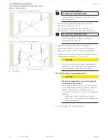
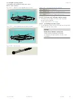
Fig. 9.2.1 Center of revolving door axis
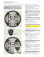
Fig. 9.2.2 Laser level measuring points
3
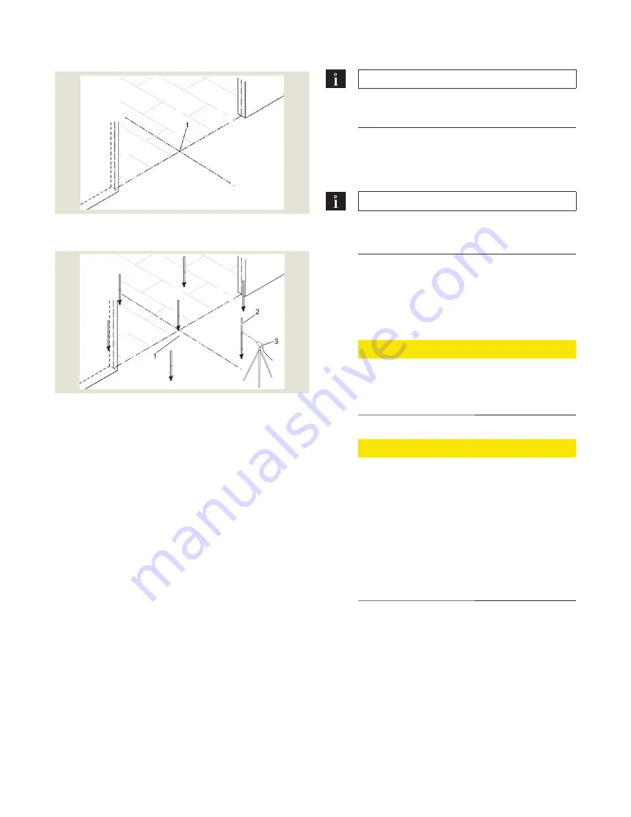
Laser leveling device
9.2.2 Check level of finished floor.
TIPS AND RECOMMENDATIONS
Check floor level procedure in Para. 9.2.2 is a
recommendation.
1. Position leveling device horizontally in front of
assembly surface (Fig. 9.2.2).
2. Position leveling staff vertically at any point on
assembly floor surface to select a reference point.
TIPS AND RECOMMENDATIONS
The reference point (step 2) is used for the
following measurements.
3. Measure reference point and note reading.
4. Take measurements at a minimum of 6 different
points, as shown in Fig. 10.4.2 and note readings.
5. Compare measurement points with reference value.
The deviation tolerance is 1/16" [2 mm].
CAUTION
If measurements are outside of the deviation
tolerance, the finished floor must be reworked
or re-prepared by the building contractor.
9.2.3 Mark center of revolving door axis.
CAUTION
Material damage due to incorrect marking of
revolving door axis center!
Inaccurate marking of the center of the axis of
the revolving door on the assembly surface can
lead to subsequent discrepancies during
assembly. This can result in faults and material
damage.
• Always accurately mark the axis center.
• Always use the supplied drilling template to
mark hole locations.
1. Go to Chapter 10, Floor template.
1
Axis
center
1
Axis
center
2
Leveling
staff


