background image

42

Crane 4000LE

07-2022

RL6002-001

Crane 4000LE Installation Manual

In-ground Motion Assist 360 drive and speed control

Remote control enclosure

Chapter 12

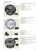
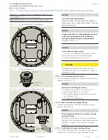
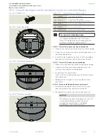
12.3  Install leveling plate in pit

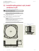
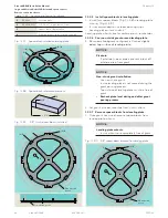
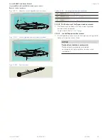
12.3.1  Install set screws in leveling plate.

1.  Install four set screws RF6028 in leveling plate.

•  Install set screws to an equal depth of  5/8" below 

leveling plate (Fig. 12.3.4).

Fig. 12.3.1  Leveling plate RC6022

1

(4) 

2

Fig. 12.3.2  Leveling plate with set screws installed

2

Fig. 12.3.3  Set screw RF6028-01G

1

(4)

 2

 2

5/8” 

Fig. 12.3.4  Set screw depth

1

RC6022

Leveling plate

2

RF6028-01G

1/2-13 x 2" cup point set screw

Table 12.3.1 

Leveling plate and hardware

Summary of Contents for Crane 4000LE

Page 1: ...Crane 4000LE In ground Motion Assist 360 drive and speed control Remote control enclosure Installation Manual RL6002 001 07 2022 EN ...

Page 2: ...t 23 5 18 Floor grill and pan assembly option 24 5 19 Uninterruptible Power Supply UPS option 24 6 In ground container hardware 25 6 1 In ground container assembly 25 6 2 Motion Assist 360 extension cables to remote enclosure 26 6 3 Motion Assist 360 earth grounding cable 26 6 4 Service panel communication cable 26 6 3 In ground container assemblies with fastener hardware 27 6 4 Container lids and...

Page 3: ...Attach Muntin assembly to header bars 71 14 9 Enclosure base and post numbering 72 14 10 Set enclosure level square and plumb 72 15 Install enclosure glass 73 15 1 Unpack enclosure glass shipping crate 73 15 2 Install glazing tape for enclosure glass 74 15 3 Install enclosure glass 75 16 Glass canopy installation with muntin 77 16 1 Glass canopy and hardware 77 16 2 Install header gaskets muntin g...

Page 4: ...document is transferred as well 1 4 dormakaba us website Manuals are available for review download and printing on the dormakaba us website 1 5 Symbols used in these instructions WARNING This symbol warns of hazards which could result in personal injury or threat to health NOTICE Draws attention to important information presented in this document CAUTION Warns of a potentially unsafe procedure or ...

Page 5: ...glass AL4000 with center post 2 1 2 Door wings 1 Herculite formed stainless steel formed bronze 2 Patch fitting extruded aluminum cladded in formed stainless steel formed bronze formed aluminum custom cladded in factory 3 Cladded herculite aluminum formed stainless steel formed bronze custom cladded and finished in factory 2 1 3 Canopy 1 All glass 13 16 laminated float glass PVB interlayer dependi...

Page 6: ...t GFCI Circuit breaker 15 A Power supply control voltage 24 10 Vdc Maximum supply current for external connections 3 Adc 2 4 3 Power consumption Measurement Value Unit Positioning speed 58 W Automatic mode 102 W Speed limiter 8 W Servomatic 58 W 2 4 4 Drive Measurement Value Unit Type Synchronous motor with continuous magnet rotor Nominal voltage 24 Vdc Nominal output 0 58 KW Nominal torque 40 Nm ...

Page 7: ...ror Non directional Jitterbug Custom Satin and lacquered Satin no lacquer Mirror and lacquered Statuary and lacquered Custom Operation Manual with Motion Assist 360 drive Attachment Types C D F G K L P Q R as indicated on the drawings Reference Chapter 5 Enclosure material Glass Aluminum panels Glass SS panel Glass Bronze panel Enclosure glass 9 16 bent laminated float glass 7 16 bent laminated fl...

Page 8: ...r electrical short circuits is possible Never put the revolving door into operation without an earth ground connected to the drive grounding terminal Prior to drive commissioning drive components must be connected to the grounding terminal Control unit Power supply unit Drive unit support system 3 Safety information WARNING Metallic doors must be grounded per national and local codes WARNING Hand ...

Page 9: ...s through at entrances and in the interior of buildings Wing breakout The revolving door wings can be pushed open manually for emergency egress WARNING In case of emergency revolving door can be used as an exit but it is not the primary path of egress The side door s should be used The customer can only operate the revolving door after door commissioning by dormakaba service technicians Intended u...

Page 10: ...access devices such as keypads card readers and key switches 4 1 4 Mode switch low energy functions Mode switch position Function S Green module Motion Assist 0 Off Revolving door will stay in the home position After a set period of time any internal lighting is switched off 1 AUTOMATIC 1 A knowing act Para 4 1 3 switch starts rotary movement of the door wings at low energy speed Para 4 1 2 Accele...

Page 11: ...NING Risk of injury due to deactivated safety equipment After the emergency stop is activated the drive is unlocked Safety devices are no longer in operation This can cause serious injuries if attempts are made to turn the door manually Before turning door manually check to make sure no one could be injured If people have been locked into the revolving door carefully turn the door until the people...

Page 12: ...tarts rotary movement of the door wings at low energy speed Para 4 1 2 Fig 4 4 1 WavetoOpen plate DX3331 001 Fig 4 4 2 PushtoStartplate 1 5x4 75 DX3339 040 4 5 1 Fault LED Fault LED provides Error number indication Frequency and rate of LED flashes indicates Error number 4 5 2 Fault LED location Field installed above or below Mode switch 4 5 3 Error number and LED blinking codes First digit of Err...

Page 13: ... control Remote control enclosure Chapter 5 Fig 5 1 1 4 wing door Fig 5 1 2 3 wing door 5 1 Door configurations In ground Motion Assist 360 drive and speed control 5 Revolving door assemblies NOTICE Refer to Crane Shop drawings for door and canopy assembly detail for specific job 5 1 2 4000LE door configurations ...

Page 14: ...s for canopy design for specific job 1 Canopy glass 2 Muntin Fig 5 3 2 Bearing assembly RS6064 1 2 3 4 5 Fig 5 2 2 Canopy glass with muntin top view 1 1 2 5 3 Muntin and bearing assembly Fig 5 3 1 Muntin top bottom and cover removed views 3 Bearing assembly Part Assembly Description 1 RC6244 0X0 Bearing mounting bracket 2 RC6234 010 Bearing block 3 RF6109 01G Ball bearing 4 RF7021 01G 8 32 x 1 2 P...

Page 15: ...360 drive and speed control Remote control enclosure Chapter 5 5 4 Glass canopy with bearing assembly Fig 5 4 1 Canopy glass with bearing assembly top view TIPS AND RECOMMENDATIONS Reference Crane shop drawings for canopy design for specific job Fig 5 4 2 Bearing assembly 1 1 Bearing assembly ...

Page 16: ...ng floor speed control 4 RC6084 001 Steel shaft cover 4 wing floor speed control 5 RC6081 001 Top plug steel shaft ground speed control 7 length 6 RC6082 001 Bottom plug steel shaft floor speed control 7 RF6052 010 Steel shaft cross pin 1 1 2 long 8 RF6053 01G 25 OD x1 2 spring pin slotted 9 RC6078 001 Weatherstrip steel shaft 10 RF6054 01G 8 32 x 1 2 Phillips FH machine screw 11 RD6001 001 Shaft ...

Page 17: ...4 001 3 wing disc assembly 4 RC6085 001 Steel shaft cover 3 wing floor speed control 5 RC6081 001 Top plug steel shaft ground speed control 7 length 6 RC6082 001 Bottom plug steel shaft floor speed control 7 RF6052 010 Steel shaft cross pin 8 RF6053 01G 25 OD x1 2 spring pin slotted 9 RC6078 001 Weatherstrip steel shaft 10 RF6054 01G 8 32 x 1 2 Phillips FH machine screw 11 RD6001 001 Shaft ID tag ...

Page 18: ...breakout force ball is rotated from detent block in disc 4 Minimal pressure is then required to continue bookfolding Wings bookfold either way providing a clear passage on both sides Fig 5 7 1 Shaft hanger assembly 5 7 Hanger assembly steel shaft RS6045 0X0 Part Assembly Description 1 RC6369 0X0 Hanger body 2 RC6156 01G Hex bolt 0 375 16 x 4 3 Lock washer 3 8 4 Hex nut 0 375 16 5 Spring 6 Ball 7 8...

Page 19: ...nt stile Herc AL Blk 2 RE6026 0X0 Rail end Herc 3 Wing glass 4 RC6389 Sweep felt vertical 5 Sweep felt top 6 Sweep felt bottom 7 RF2961 Wing bumper assembly not shown 8 Wing push bar Push bars ordered job specific for each order 9 76019184 Cylinder assembly Table 5 10 1 Door wing assembly and part examples NOTICE Refer to Crane Shop drawings for wing detail for specific job 5 11 Door wing types Fi...

Page 20: ...nce Crane shop drawings for header bar design for specific job Fig 5 12 1 Header bar assembly Fig 5 12 2 P OVHMS 4 Part Assembly Description 1 Header bar 2 Header bar inner plate 3 Header bar outer angle 4 RF6123 01G 8 32 x 1 1 2 Phillips oval head MS Table 5 12 1 Header bar assembly 2 1 3 4 Part Assembly Description 1 Floor bar 2 Floor bar outer plate 3 Floor bar inner plate 4 Compressed 1 8 glaz...

Page 21: ...t SS 11 RF6022 3 8 16 x 7 8 socket head cap screw with thread lock 12 RF6024 3 8 16 x 1 2 Phillips flat head screw 13 RF6025 01G 1 4 20 x 3 4 sealing FH countersunk screw 14 RF6026 01G 10 32 x 3 8 sealing FH countersunk screw 15 RS6014 Leveling plate assembly 16 RS6033 Outer cover assembly 17 RC6060 Motion Assist 360 drive mounting bracket 18 RX6010 Motion Assist 360 drive 19 RS6024 Container asse...

Page 22: ...many IP20 month year System Speed Limiter Positioning Automatic Static force Servomatic Static force Automatic Static force 58 W 8 W 150 N 67 N 58 W 67 N 1 2 3 0 102 W KT FLEX Direct drive system Art Nr 34050001150 100 240V 50 60 Hz 40 60 C 5 3 5 4 0 DIN 18650 Made in Germany DORMA Deutschland GmbH Dorma Platz 1 58256 Ennepetal Germany IP20 month year System Speed Limiter Positioning Automatic Sta...

Page 23: ...17 1 Motion Assist 360 Remote enclosure Fig 5 17 4 Motion Assist 360 power supply and cables Fig 5 17 2 Motion Assist 360 control unit Fig 5 17 3 S functionmodule Grn MotionAssist 1 1 1 1 2 1 3 2 3 Table 5 17 1 Remote enclosure hardware Part Assembly Description 1 RX6001 001 Motion Assist 360 power supply 1 1 115 Vac cable to control unit 2 1 2 DC cable to control unit 2 1 3 Plug for customer 115V...

Page 24: ... 19 2 UPS power supply units option Fig 5 19 2 Motion Assist 360 power supply UPS Part Rating Maximum time VA Watts 12 foot diameter door RX6011 001 1500 900 3 hours RX6012 001 500 300 1 hour 7 foot diameter door RX6011 001 1500 900 4 hours RX6012 001 500 300 1 5 hours Fig 5 19 1 UPS 115Vac to MotionAssist 360 power supply 2 1 UPS unit Customer 115 Vac 1 UPS 115 Vac output to Motion Assist 360 pow...

Page 25: ...container assembly Fig 6 1 1 In ground drive assembly with speed control and bottom plug installed 2 Table 6 1 1 Motion Assist 360 drive hardware Part Assembly Description 1 RX6010 Motion Assist 360 drive 2 RS6074 010 In ground speed control 3 RS6038 Container assembly weldment 4 RC6043 Drain plug 5 RC6048 Floor cover plate 6 RC6005 001 DC conduit adapter 1 1 2 7 RS6014 Leveling plate assembly 1 2...

Page 26: ...1 RX6016 001 Motor extension cable 25 standard Optional motor extension cables RX6016 002 Motor extension cable 50 RX6016 003 Motor extension cable 100 2 RX6015 001 Hall sensor extension cable 25 standard Optional Hall sensor extension cables RX6015 002 Hall sensor extension cable 50 RX6015 003 Hall sensor extension cable 100 Table 6 2 1 Motion Assist 360 drive extension cables 6 2 1 Motion Assist...

Page 27: ...ntainer leveling plate assembly hardware 4 1 4 2 1 2 ID Part Description Qty 1 RX6010 Motion Assist 360 drive 1 2 RC6060 Motion Assist 360 drive mounting plate 1 6 RF6010 01G Washer flat 1 1 4 OD 0 531 ID for 1 2 screw SS 4 7 RF6004 01Z Hex head cap screw M10 x 40 mm class 12 9 zinc extreme strength 4 8 RF6005 01G Nylon insert locknut M10 SS 4 6 3 1 Container leveling plate hardware 6 3 2 Motion A...

Page 28: ...ide 3 6 3 4 In ground speed control to container assembly fasteners 11 10 6 Fig 6 3 6 Cable tie fastener ID Part Description Qty 12 RC6042 Wire tie fastener 14 RF6024 01G 6 x 1 2 Phillips FHS SS 8 6 3 6 Cable tie fastener 14 12 14 Fig 6 3 7 Fasteners container lids ID Part Description Qty Floor cover plate fasteners 12 RF6026 01G 10 32 x 3 8 sealing flat head screw SS 16 Container lid fasteners 13...

Page 29: ...6 Fig 6 4 2 Outercoverassembly topandbottomviews Fig 6 4 1 Containerlid centersection Fig 6 4 4 Floorcoverplates 5 5 ø32 00 4 Fig 6 4 3 Flangegasket 3 6 4 Container lids and cover assemblies 2 2 ID Part Description 2 RS6033 Outer cover assembly 3 RC6049 Container lid center section 4 RC6046 Flange gasket 5 RC6048 Floor cover plate 6 4 1 Cover assemblies ...

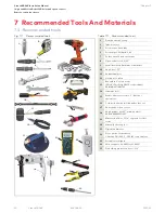
Page 30: ...r 10 Spirit level 72 11 Rubber hammer 12 Needle nose pliers 13 Bent glass 9 suction cups Wood s Pwr Grip N5450 or equivalent ASIN B007IAB3TM 14 Hammer drill 15 Rotary hammer core bit 5 Bosch or equivalent 16 Cordless drill with drill bit and socket set 17 Razor knife or box cutter 18 Angle grinder with 5 grinding wheel ASIN B00EMFOKSC 19 Masonry drill bits 1 1 4 required for floor strike 20 Manual...

Page 31: ...ring springs CRL W516 ASIN B006JFMQUM 6 White lithium grease for center shaft assembly ASIN B06XY6QK57 7 Posi Twist Bundle kit ASIN B000JP3GB6 8 Rockite quick drying cement ASIN B000BO9JRK 1 16 x 1 2 1 2 x 1 2 1 Fig 7 2 1 Recommended installation materials 3 5 6 7 10 2 4 Table 7 2 2 Recommended installation hardware 8 Description 10 Metaltech wall hauler 2000 series drywall cart ASIN BMD2131YGR 11...

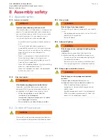
Page 32: ...supply are energized Touching the components poses an immediate risk of death from electric shock When laying cables ensure that the insulation is not damaged Immediately Replace components or cables with damaged insulation Do not place or set down loads on cables 8 1 3 Heavy loads WARNING Risk of injury from heavy loads Manual lifting of heavy components can lead to injury Use appropriate equipme...

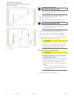
Page 33: ...roper leveling Laser leveling device with stand Improper positioning of the stand or leveling staff may lead to measurement errors when leveling Measurement errors can lead to incorrect assembly of the revolving door This will result in material damage Before leveling ensure that the stand is securely positioned on the floor and cannot wobble or tilt Before leveling ensure that the laser leveling ...

Page 34: ... Measure reference point and note reading 4 Take measurements at a minimum of 6 different points as shown in Fig 10 4 2 and note readings 5 Compare measurement points with reference value The deviation tolerance is 1 16 2 mm CAUTION If measurements are outside of the deviation tolerance the finished floor must be reworked or re prepared by the building contractor 9 2 3 Mark center of revolving doo...

Page 35: ...TIONS Templates for canopy diameters greater than 6 6 I D are custom made and cut out of a Masonite type material to match door conditions Fig 10 1 Full size floor template AL4000 3 wing full round door example 1 Locate full size template Template shipped in canopy shipping crate 2 Reference Crane shop drawing for template orientation at building attachment Fig 10 2 Full size floor template AL4000...

Page 36: ... location on sub floor install base rail assemblies 11 1 Mark door centerpoint 11 1 1 Locate and mark door centerpoint 1 Use floor template Chapter 10 and contractor architect drawings to determine door centerpoint 2 Use plumb bob with string or a laser plumb bob to mark door centerpoint location on subfloor Fig 11 1 1 Crane AL4000LE shop drawing Plan and Elevation view example ...

Page 37: ... to Para 12 9 for post numbering locations Fig 11 2 2 Base rail assemblies placed on subfloor Fig 11 2 1 Floor template dimensions Base rail outer radius Base rail inner radius Enclosure radius Building interface Base rail outer radius Base rail inner radius Building interface Base rail base clip assembly Base rail base clip assembly 1 Locate base rail assemblies Fig 11 3 1 on subfloor Check that ...

Page 38: ... 3 11 4 1 3 3 4 to 4 slab depth to finished floor Fig 11 4 1 NOTICE 0 to 1 4 allowable shimming below floor clip 1 4 20 x 1 2 FHMS by Crane Installer must select appropriate length floor clip concrete fastener 11 4 2 3 3 4 to 5 slab depth to finished floor Fig 11 4 2 NOTICE 0 to 1 allowable shimming above floor clip 0 to 1 4 allowable shimming below floor clip 1 4 20 x 1 1 2 FHMS by installer Inst...

Page 39: ... 3 4 To 4 slab depth to finished floor Fig 11 4 2 3 3 4 to 5 slab depth to finished floor 3 3 4 To 5 slab depth to finished floor 0 to 1 allowable shimming 0 to 1 4 allowable shimming 1 4 20 x 1 1 2 FHMS by installer Fig 11 4 3 4 to 6 slab depth to finished floor 4 to 6 slab depth to finished floor 0 to 1 allowable shimming 1 4 20 x 1 1 2 FHMS by installer 1 4 20 fasteners or welded by installer 5...

Page 40: ...ed at door centerpoint 12 1 2 Verify pit dimensions for in ground drive assembly 1 Verify minimum pit dimensions NOTICE Pit centerpoint and or pit dimension issues Resolve any pit door centerpoint location or pit dimension issues with building contractor before proceeding Fig 12 1 1 Minimum pit dimensions 12 Install leveling plate in pit install container in pit Finish floor line 10 3 4 minimum 1 ...

Page 41: ...L6002 001 Crane 4000LE Installation Manual In ground Motion Assist 360 drive and speed control Remote control enclosure Chapter 12 12 2 Crane Shop drawing pit dimensions for in ground container Fig 12 1 1 Minimum pit dimensions ...

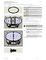
Page 42: ...s in leveling plate 1 Install four set screws RF6028 in leveling plate Install set screws to an equal depth of 5 8 below leveling plate Fig 12 3 4 Fig 12 3 1 Leveling plate RC6022 1 4 2 Fig 12 3 2 Leveling platewith set screws installed 2 Fig 12 3 3 Set screwRF6028 01G 1 4 2 2 5 8 Fig 12 3 4 Set screwdepth 1 RC6022 Leveling plate 2 RF6028 01G 1 2 13 x 2 cup point set screw Table 12 3 1 Leveling pl...

Page 43: ...erpoint 12 3 4 Level and adjust height of leveling plate NOTICE Adjust four set screws 2 to obtain a leveling plate height top surface of 13 3 4 to finish floor line Fig 12 3 5 Check leveling plate for level Recheck that leveling plate is at door centerpoint and is parallel to building interface Fig 12 3 6 Fig 12 3 5 Leveling plate installation 1 4 2 Pit Door centerpoint c Building interface L 3 1...

Page 44: ...nk grout Insure leveling plate is not moved during the grout pouring process Top surface of leveling plate must be free of grout Recheck plate level during and after grout pouring process 2 Let grout cure per manufacturer s instructions 12 3 7 Remove spacer blocks from leveling plate 1 Once grout has cured remove spacer blocks from leveling plate cutouts NOTICE Leveling plate cutouts Insure cutout...

Page 45: ...Tapcon anchor screws 1 Install Tapcon anchor screws through mounting plate holes into anchor screw holes NOTICE Recheck level and door centerpoint Recheck leveling plate level and door centerpoint during and after anchor screw installation Fig 12 3 11 Holesformounting plate anchorscrews Fig 12 3 12 Mounting plate anchorscrews installed Fig 12 3 13 Anchorscrew 5 4 2 4 5 1 1 4 2 4 4 4 4 1 RC6022 Lev...

Page 46: ...tainer conduit adapter entrance location Reference Para 12 6 to determine container orientation for building conduit interface to 1 1 2 DC conduit adapter TIPS AND RECOMMENDATIONS Orientation of container DC conduit adapter in pit must be determined before locating position of through wall pipe fitting for container drain Reference Para 12 6 Fig 12 4 1 Container lids parallel to building interface...

Page 47: ...duit 1 DC wiring 1 1 2 liquid tight conduit adapter is supplied for interfacing to building liquid tight flexible conduit NOTICE Building contractor responsibilities Plan routing of building liquid tight flexible conduit in pit to container conduit adapter locations Terminate conduit into liquid tight conduit adapter Reference Para 12 11 12 5 Conduit in pit for building wiring overview Fig 12 5 3 ...

Page 48: ...rfaces to in ground container Reference Wiring Setup and Troubleshooting Manual RL6002 003 NOTICE Building conduit Review orientation of container in pit with dormakaba technician Para 12 4 Plan routing of building liquid tight flexible conduit to container conduit adapter entrance location Building conduit for container 1 1 2 conduit adapter must be installed into pit prior to installation of con...

Page 49: ...in ground container into pit 12 7 1 Container provisions for drain 1 Four areas are provided in container for through wall pipe fitting Fig 12 7 1 NOTICE Review with building contractor 1 Container orientation in pit Para 12 4 2 Drain area locations in container 3 Required container orientation for conduit entry Para 12 6 3 Through wall pipe fitting 12 7 2 Determine location of pipe fitting 1 Dete...

Page 50: ...n Assist 360 drive and speed control Remote control enclosure Chapter 12 Fig 12 81 In ground container drain hole locations template Fig 12 8 2 Leveling plate drain hole locations template 47 4 8 5 Ø1 63 12 8 Container drain hole location dimensions using leveling plate 47 4 8 5 Ø1 63 ...

Page 51: ...assembly hole alignment with center section container flange holes 3 Install three flat head screws Fig 12 9 4 to validate alignment of all outer cover assembly holes 4 Repeat steps 1 through 3 for second outer cover assembly 12 9 3 Remove all flat head screws and covers 1 Remove all flat head screws from the two outer covers and the center section container lid 2 Remove covers and center section ...

Page 52: ...Install two cable ties in container 1 Install two cable ties in container using 6 x 1 2 Phillips FHS Fig 12 10 1 4 cableties 12 10 Install cable ties Fig 12 10 2 Cable tie and fastener 14 14 12 12 12 2 1 2 1 Hole for through wall pipe fitting May be in a different location 12 RC6042 Cable tie 14 RF6024 01G 6 x 1 2 Phillips FHS Table 12 10 1 Cable ties and fastener ...

Page 53: ...7 Container lids parallel with building interface Para 12 4 12 11 4 Install container assembly in pit WARNING Use caution when working with container assembly Container has four eyebolts that can be used with lifting equipment 1 Align container with pit interfaces 2 Insert DC conduit adapter flexible conduit installed in adapter by customer into container adapter plate Tighten conduit adapter lock...

Page 54: ...e Chapter 12 Fig 12 11 2 Container in pit orientation example 12 11 5 Verify container is level NOTICE Once container lowered onto leveling plate verify container is level 2 Building interface 5 3 3 2 RC6012 Leveling plate 3 RC6043 Through wall pip fitting 5 RC6045 001 1 1 2 conduit adapter DC wiring Table 12 11 2 Container and leveling plate ...

Page 55: ...ntrol in container 1 Fasten in ground speed control to container speed control shims using three 3 8 x 7 8 SHCS Snug but do not tighten the socket head cap screws 13 1 Install speed control in in ground container Fig 13 1 3 In ground speed control Fig 13 1 2 Speed control mounting holes Fig 13 1 4 3 8 x 7 8 SHCS 1 2 11 11 11 Fig 13 1 1 Speed control oilfill hole 2 1 1 RS6074 010 Floor speed contro...

Page 56: ...ust be centered in center section container lid hole Fig 13 2 3 Bottom plug adapter must be plumb Speed control mounting hole diameter is 7 16 so slight adjustment is possible 4 Once bottom plug adapter centered in hole tighten the speed control 3 8 x 7 8 SHCS Fig 13 1 3 NOTICE Insure that the three 3 8 x 7 8 SHCS are securely tightened Fig 13 2 2 Bottom plug adapter installed in speed control dri...

Page 57: ...3 1 Container lids and floor cover plates hardware 13 3 1 Verify floor cover plates are flush with finished floor 1 Place flange gasket on container lid 1 Place center section container lid on container and secure with two 1 4 20 x 3 4 sealing FHS 2 Place two outer cover assemblies on container 3 Place two floor cover plates over container lids TIPS AND RECOMMENDATIONS Do not fasten outer cover as...

Page 58: ...rout 8 3 4 minimum 10 3 4 minimum Finished floor line 1 2 REF 13 4 1 Pour pour stone in pit around container case NOTICE Reference Crane shop drawings for job 1 Fill pour stone around container to 1 2 below container flange Fig 13 4 1 TIPS AND RECOMMENDATIONS Cover container lids with cardboard during pour stone fill process 13 4 Pour Pour stone around container in pit NOTICE Follow manufacturer s...

Page 59: ...during shipment Use caution when handling drive once bolts have been removed Drive is free to turn Fig 13 5 1 Drivetransportbolts nutsandwashers topview Fig 13 5 2 Drive bottomview transportbolts 3 3 1 3 4 5 3 4 5 Art Nr 34050001150 100 240V 50 60 Hz 40 60 C 5 3 5 4 0 DIN 18650 Made in Germany DORMA Deutschland GmbH Dorma Platz 1 58256 Ennepetal Germany IP20 month year System Speed Limiter Positio...

Page 60: ...rom incorrect screw tightening torque If drive flange mounting screws are tightened with an incorrect tightening torque components may detach causing injuries and material damage Never exceed the maximum specified screw tightening torque Contact dormakaba for further information 13 6 4 Maximum screw tightening torque Screw diameter Maximum permissible screw tightening torque M8 15 5 Nm 10 ft lb Fi...

Page 61: ...equirements for M10 hex head bolt Fig 13 6 8 Drive secured to drive mounting plate 1 RX6010 001 Motion Assist 360 drive 2 RC6060 Motion Assist 360 drive mounting plate 3 RF6004 M10 1 5 x 30 mm hex head bolt 4 RF6010 01G Flat washer 0 531 ID x 1 25 OD 5 RF6005 01G M10 1 5 Nylon lock nut 6 RC6025 Drive flange 4 OD Table 13 6 2 Motion Assist 360 drive and drive flange hardware 2 Fig 13 6 7 Drive to d...

Page 62: ...is fully inserted in operator socket and locked in place 2 Install Hall sensor cable plug at shield end of cable Fig 13 7 2 into Motion Assist 360 drive Hall sensor socket NOTICE Install sensor cable orientated as shown in Fig 13 7 2 Insure cable plug is fully inserted in operator socket and locked in place 6 5 Drive plug 5 1 6 1 Drive plug Choke Shield Fig 13 7 1 Motion Assist 360 drive cables Fi...

Page 63: ...bolt thread four 1 2 x 3 4 hex head bolts through mounting plate slots into U channel mounting holes 3 Snug bolts do not tighten 4 Secure cables to cable ties 9 Fig 13 8 1 Mounting bracket assembly orientation Fig 13 8 3 Container and mounting bracket assembly Fig 13 8 4 Container and mounting bracket assembly 13 8 Install Motion Assist 360 drive mounting bracket assembly 6 5 1 2 Art Nr 3405000115...

Page 64: ...n hex bolts 1 Tighten the four 1 2 x 3 4 hex bolts 13 9 4 Install foil tape over drive mounting holes 1 Install tape over Motion Assist 360 drive mounting holes Fig 13 9 4 Use foil tape must have minimum temperature range of 35 to 175 F TIPS AND RECOMMENDATIONS Tape installation to prevent moisture from entering Motion Assist 360 drive Fig 13 9 2 Bottom plug adapter installation Fig 13 9 4 Tape in...

Page 65: ...ll numbering Each post s wrapping material is marked with numbers indicating where the center posts and quarter posts end walls are to be located in the door installation Insure post is marked with its location number on the top and bottom of the post TIPS AND RECOMMENDATIONS Refer to Para 14 9 for enclosure post and base numbering example 14 2 Open post shipping crate Fig 14 2 1 Post shipping cra...

Page 66: ...rol Remote control enclosure Chapter 14 1 Quarter post end wall RE6019 010 5 Center post RE6007 0X0 6 Center post bottom plate RF6007 010 Fig 14 3 1 Quarter post end wall Fig 14 3 2 Center post 14 3 1 Quarter post end wall and center post aluminum extrusion 14 3 Quarter post end wall and center post assemblies 5 6 1 ...

Page 67: ... 4 20 threaded rod 3 Holes on he 1 4 floor bar and 1 x 3 4 outer bar opened to allow clearance for the 1 4 20 threaded rod 14 4 3 Install threaded rods into center post bottom plate 1 Thread rods into 1 4 20 tapped holes in center post bottom plate 14 4 4 Install center post onto floor bar 1 Raise center post vertically then lower center post onto floor bar Fig 14 4 3 14 4 4 14 4 5 Install second ...

Page 68: ...od 14 5 2 Install threaded rod into quarter post 1 1 4 20 x 2 threaded rod serves to align quarter post with base 2 Thread 1 4 20 by 2 threaded rod into bottom hole in quarter post 14 5 3 Place quarter post on base rails 1 Raise quarter post vertically place threaded rod into floor bar and lower assembly onto floor bar 1 2 Fig 14 5 2 Quarter post with threaded rod 1 2 Ø1 4 clearance hole 3 Fig 12 ...

Page 69: ...on first set of quarter posts and center post 1 Place header bar on first set of posts 2 Secure header bar to each quarter post using a 1 4 20 x 1 FHMS 14 6 2 Repeat steps 1 and 2 in Para 14 6 1 for second header bar and quarter posts Fig 14 6 3 Quarter post attachment to header bar assembly Fig 14 6 1 1 4 20 x 1 FHMS 1 1 2 2 5 5 Fig 14 6 2 Header bar assembly Table 14 6 1 Header bar and hardware ...

Page 70: ... for center post attachment 14 7 1 Attach center post to header bar 1 Attach center post to header bar using two 1 4 20 x 1 FHMS 14 7 2 Repeat Para 14 7 1 for second header bar and center post Fig 14 7 1 1 4 20 x 1 FHMS Fig 14 7 2 Center post attachment to header bar assembly 4 5 2 Table 14 7 1 Header bar and hardware 1 RE6019 010 Quarter post 2 Header bar assembly 4 RE6007 0X0 Center post 5 RF611...

Page 71: ...Attach muntin assembly to header bars 1 Attach muntin to header bars using two 10 24 x 1 2 FHMS on each header bar Fig 14 8 4 Fig 14 8 3 10 24 x 1 2 FHMS Fig 14 8 4 Muntin attachment to header bar assembly Fig 14 8 2 Bearing assembly Fig 14 8 1 Muntin top bottom and cover views 3 1 1 2 3 4 4 3 2 3 4 Crane shop drawing example Muntin installation 4 4 2 Table 14 7 1 Muntin assembly and hardware 2 Mu...

Page 72: ...ING Using plumb bob with string verify canopy bearing centerpoint is plumb with in ground Motion Assist 360 drive shaft centerpoint Fig 14 10 1 Enclosure check for level square and plumb Fig 14 9 1 Standard post installation numbering 4 4 3 3 1 1 1 2 2 Number stamped on base Interior Exterior Post number 2 3 4 Post numbering starts on the interior side ascending in a CW orientation Door 1 Post num...

Page 73: ...ation details for job 15 1 2 Unpack shipping crate 1 Uncrate enclosure glass from shipping crate CAUTION Refer to warning tag on shipping crate regarding unpacking procedure CAUTION Use caution when handling glass to prevent scratching or damage to glass surfaces CAUTION Handle curved glass with care Do no exert force on the glass pieces WARNING Use caution while working with enclosure glass Clean...

Page 74: ...all compressed 1 8 glazing tape 15 2 2 Install glazing tape in enclosure posts 1 Install compressed 1 8 glazing tape in center post Fig 15 2 1 and quarter post Fig 15 2 2 15 2 3 Install glazing tape in header bars 1 Install compressed 1 8 glazing tape in header bars Fig 15 2 3 Fig 15 2 1 Enclosure base glazing block and glazing tape center post glazing tape 4 2 Fig 15 2 2 Enclosure base and quarte...

Page 75: ...ing with the glass 15 3 1 Install glazing block in base rail 1 Install glazing block in base rail Fig 15 2 4 15 3 2 Set first enclosure bent glass into place 1 Set enclosure glass into place centering the glass between the vertical posts 15 3 3 Install glazing block in header bar 1 Install 1 glazing block between header bar and glass 15 3 Install enclosure glass Fig 15 3 1 Enclosure glass installa...

Page 76: ...stall header cover 1 Install header cover using three 8 32 x 1 1 2 oval machine screws 15 3 6 Install header backer rod 1 Install backer rod between header cover and glass 15 3 7 Install remaining enclosure glass 1 Install remaining enclosure glass per paragraphs 13 3 1 through 13 3 6 15 3 8 Complete glazing of enclosure glass 1 Finish enclosure glazing Enclosure glazing per Crane shop drawings Fi...

Page 77: ...utton with rod and gasket 16 Glass canopy installation with muntin 1 1 2 3 Fig 16 1 1 Glass canopy assembly top view 1 1 2 3 4 5 Fig 16 1 2 Glass canopy assembly bottom view Fig 16 1 3 Header gasket Table 16 1 1 Glass canopy and hardware 1 13 16 polyurethane laminted float glass 2 Canopy muntin assembly 3 1 diameter attachment button 3 1 Gasket 3 2 1 4 20 x 1 5 8 threaded rod 4 RS6064 001 Bearing ...
Page 78: ...untin installation Refer to Para 14 8 for muntin installation 16 2 4 Install muntin backer rods 1 Install backer rod by installer on each side of muntin 16 2 5 Install muntin glazing tape 1 Install glazing tape by installer on each side of muntin 16 2 Install header gaskets muntin glazing tape and backer rods 5 6 7 5 5 5 5 Fig 16 2 1 Muntin backer rod and glazing tape header bar gasket 16 3 Canopy...

Page 79: ... over header bar gaskets and muntin glazing tape 3 Lower canopy glass onto header bar gaskets and muntin glazing tape Glass must be against muntin backer rod Glass mounting holes for button head screws must be lined up with header bar mounting holes 4 Repeat steps 1 through 4 for second canopy glass section 5 Install button head screws twp per glass section 6 Install muntin backer rods Fig 16 4 2 ...

Page 80: ...ons of operator control hardware must be reviewed with site contractor or owner 17 5 2 Remote control enclosure wiring setup troubleshooting and maintenance instructions Refer to Manual RL6002 003 for wiring interfaces to Remote control enclosure Table 17 5 1 Operator control hardware Part Assembly Description 1 DX4604 08C RH45 service panel option 2 RX6013 Fault LED 3 RX6008 Mode switch 4 RX3413 ...

Page 81: ...y RS6061 001 3 wing steel shaft assembly CAUTION Refer to warning tag on shipping crate regarding unpacking procedure WARNING Use caution when lifting and positioning center shaft assembly NOTICE Refer to Crane shop drawings for specific center shaft detail for job 18 2 Remove center shaft assembly from shipping crate 1 Plug for overhead bearing TIPS AND RECOMMENDATIONS For center shaft assembly a...

Page 82: ...s injuries and material damage A minimum of two persons are always required to lift or move the center shaft assembly 18 3 1 Remove nameplate job number tag 1 Remove two Phillips pan head screws securing nameplate to center shaft and set aside 2 Remove nameplate job tag and set aside TIPS AND RECOMMENDATIONS Nameplate tag must be retained and reinstalled after installation of center shaft Refer to...

Page 83: ...NS Prior to installation lubricate center shaft bottom plug with a multipurpose grease TIPS AND RECOMMENDATIONS Grout not shown in cement box 18 4 2 Lower center shaft bottom plug into bottom plug adapter 1 Rotate center shaft assembly as required to orient bottom plug to bottom plug adapter 2 Lower center shaft bottom plug into bottom plug adapter 3 Thread 5 16 x 1 2 SHCS into bottom plug adapter...

Page 84: ...ate job number tag 1 Place nameplate job number tag over set screw and secure with two 6 32x1 4 Phillips pan head screws CAUTION Nameplate and job number tag must be reinstalled Tag job number is important reference number for any future service work 18 5 3 Set hanger initial bookfold tension Go to Chapter 19 Set hanger initial bookfold tension Fig 18 5 3 Nameplate installed 18 5 Install center sh...

Page 85: ...gainst spring 3 Using open end 9 16 box wrench turn hex nut 4 four turns CW to tension spring 4 Turn hex nut 3 until it is against 4 5 Use 9 16 wrenches to lock hex nuts in place NOTICE Reference Chapter 22 for breakout force check after wings are installed Further adjustment of spring tension on all hangers may be required to achieve required wing breakout force 19 1 3 Remaining hangers 1 Repeat ...

Page 86: ...e caution when handling wing assemblies to prevent scratching or damage to wing or glass surfaces WARNING Use caution while working with wing assemblies WARNING Risk of injury due to improper handling of wing assemblies A minimum of 2 people are required to lift and transport wing assemblies Fig 20 1 2 Wing assembly example 20 Winginstallation 1 2 2 3 4 5 6 8 Part Assembly Description 1 RE6038 0X0...

Page 87: ... A minimum of two people are required to lift and transport wing assemblies 1 Slide wing over top and bottom hangers 2 Secure wing to top hanger with two truss head machine screws 3 Secure wing to bottom hanger with two truss head machine screws 20 2 2 Install remaining wings on center shaft hangers 1 Install remaining wings 20 2 Install wings onto center shaft hangers Fig 20 2 2 Wing and hanger m...

Page 88: ...N Drill must be perpendicular to floor 2 Repeat step 1 for second floor strike 21 1 4 Clean any dirt and debris from floor strike holes CAUTION Insure floor strike holes are clear of dirt and debris 1 Use a vacuum or blower to remove any debris inside each hole 21 1 5 Install floor strikes 1 Fill hole with grout Use a grout such as QUIKRETE FastSet non shrink grout 2 Place floor strike in hole 3 T...

Page 89: ...wer hangers Use open end 9 16 box wrench for tension adjustment Monitor number of hex nut turn adjustments made so that the same number of adjustments can be made on the lower hanger Increase hanger tension Turn hex nut 6 CW to tension spring Use two 9 16 wrenches to both lock hex nuts in place Repeat same tension adjustment on lower hanger Decrease hanger tension Turn hex nut 6 1 CCW to allow red...

Page 90: ... Doorwing in breakout position Fig 22 2 1 Doorwings in bookfold position 22 1 5 Breakout force remaining wings 1 Check breakout force on each of the remaining wings 2 Adjust breakout force as required on hangers for each wing to meet requirements in Para 21 1 1 22 2 Check bookfold operation 22 2 1 Check wing bookfold operation 1 Check bookfold operation on all wings ...

Page 91: ...91 Crane 4000LE 07 2022 RL6002 001 Crane 4000LE Installation Manual In ground Motion Assist 360 drive and speed control Remote control enclosure Blank page This page left intentionally blank ...

Page 92: ...www dormakaba us dormakaba DORMA USA Inc 1 Dorma Drive Drawer AC Reamstown PA 17567 USA T 717 336 3881 F 717 336 2106 ...

Reviews: