54
ED50
08-2018
DL4614-140
dormakaba ED50 OHC Installation Instructions
Chapter 26
26.1 Customer 115 Vac connection
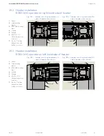
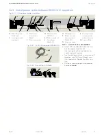
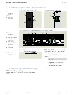
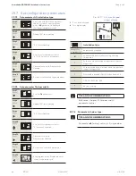
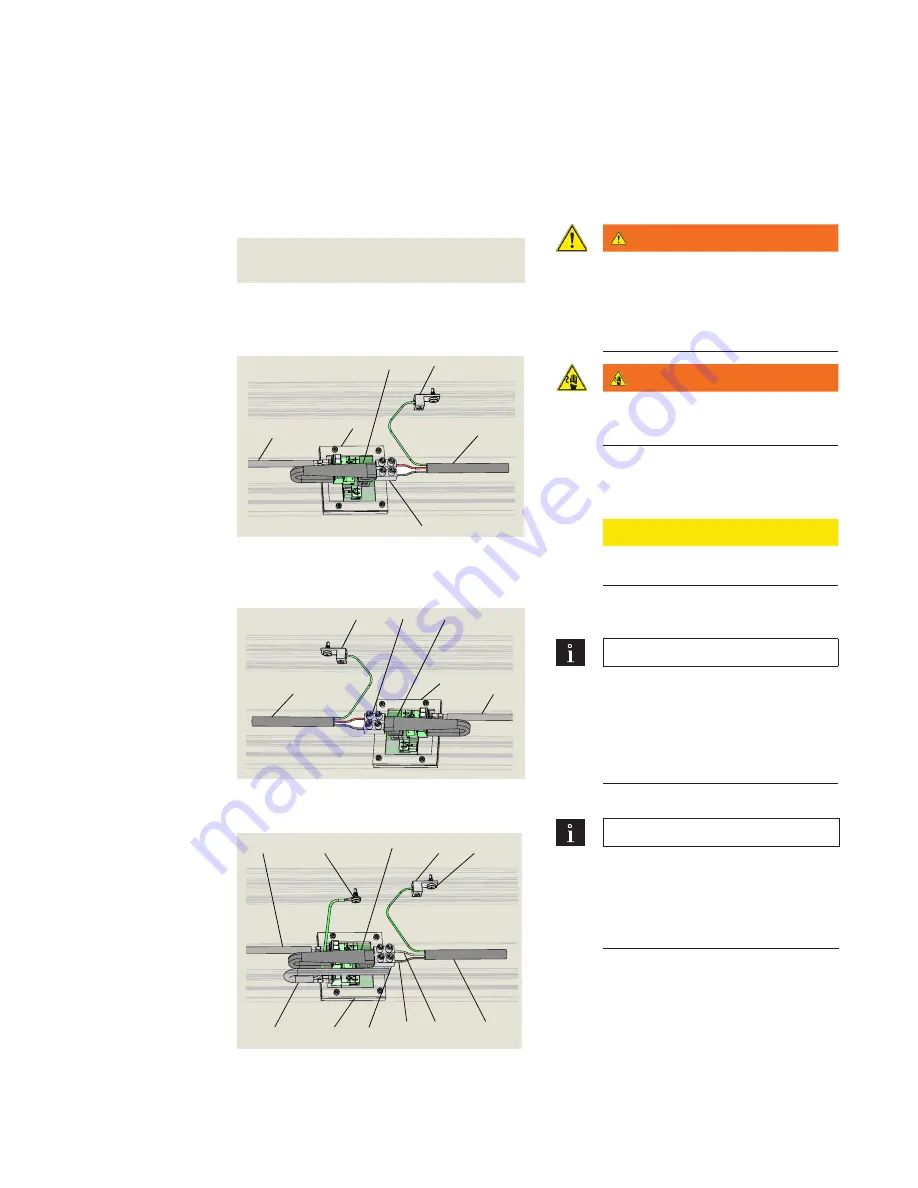
Fig. 26.1.4 Customer 115 Vac connection,
double door header
26 Customer 115 Vac connection
26.1.1 Connect 115 VAC wiring.
WARNING
Routing and connection of 115 VAC
wiring to ED50 OHC operator
must be performed by a qualified
person!
WARNING
115 VAC branch circuit disconnect
or circuit breaker must be OFF!
1. Route wiring into header, use
appropriate fittings to secure wiring, and
route wiring to 115 VAC terminal block.
CAUTION
Use copper conductors only!
2. Terminate 115 VAC wiring at power
cable terminal block.
TIPS AND RECOMMENDATIONS
• Maximum wire strip length, 1/4".
• Tighten terminal screws to
torque referenced in Fig. 26.1.1.
• Leave service loop in wiring at
terminal block for maintenance.
3. Terminate ground wire at ground lug.
TIPS AND RECOMMENDATIONS
Install label in header with
panelboard and circuit breaker
number supplying 115 Vac to
header.
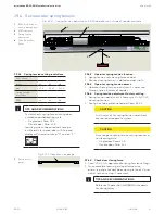
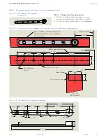
TIGHTEN MAINS TERMINAL TO 5-7 in-lb
Use Copper Conductors ONLY
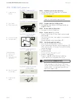
Fig. 26.1.1 115 Vac terminal torque and wire
label
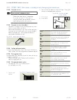
4
115 Vac power
extension cable
DX4647
5
115 Vac power module
5.1
Main power cable
DK3772-010
5.2
115 Vac terminal block
6
Ground lug kit
DK4656-010
6.1
Self tapping screw
7
115 Vac power cable
DX3484-030
10
Customer 115 Vac
5
5.1
10
6.1
6.1
6
115
Vac
N
7
4
5.2
Fig. 26.1.2 115 Vac connection; ED50
operator left side of header
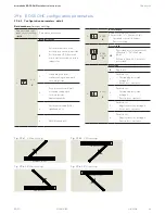
4
115 Vac power
extension cable
DX4647
5
115 Vac power module
5.1
Main power cable
DK3772-010
5.2
115 Vac terminal block
6
Ground lug kit
DK4656-010
10
Customer 115 Vac
10
6
4
5
5.1
5.2
Fig. 26.1.3 115 Vac connection; ED50
operator right side of header
6
5.1
10
4
5
5.2
4
115 Vac power
extension cable
DX4647
5
115 Vac power module
5.1
Main power cable
DK3772-010
5.2
115 Vac terminal block
6
Ground lug kit
DK4656-010
10
Customer 115 Vac

