16
ED50
08-2018
DL4614-140
dormakaba ED50 OHC Installation Instructions
Chapter 7
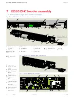
7.1 ED50 OHC single door header example
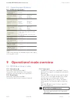
7 ED50 OHC header assembly
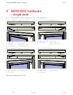
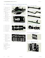
Fig. 7.1.1 ED50 OHC header and operator assembly, LH outswing
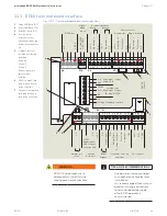
1
OHC header, LH
outswing
2
ED50 operator
2.1
Mounting plate
2.2
Control board
2.3
115 Vac cable
3
Jamb bracket
4
End cap
5
Ribbon cable
6
Low voltage wiring
connection PCB
module
7
115 Vac power
extension cable
8
115 Vac power cable
9
115 Vac power
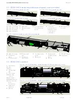
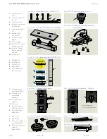
1
Control board
2
Keypad and 2 digit
display
3
Braking circuit plug
4
Power fail closing
speed
potentiometer
5
Upgrade card slot
5.1
Upgrade card
socket
6
dormakaba handheld
communication port
7
Pair door operator
to operator
communication port
8
Ribbon cable socket
9
Program switch
panel socket
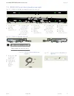
Fig. 7.1.3 ED50 operator control board
1
2
3
4
5
5.1
6
7
8
9
2
5
6
7
2.1
9
2.2
2.3
8
8.1
connection PCB
module
10
Ground lug
8.1
Fig. 7.1.2 ED50 OHC operator cables and modules
Reference Chapter 26
for 115 Vac customer
connection
8.1
115 Vac terminal
block
1
6
7
8
9
4
3
3
4
2
5
10
8.1

