21
ED50
08-2018
DL4614-140
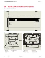
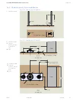
dormakaba ED50 OHC Installation Instructions
Chapter 10
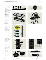
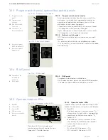
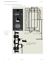
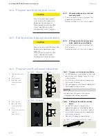
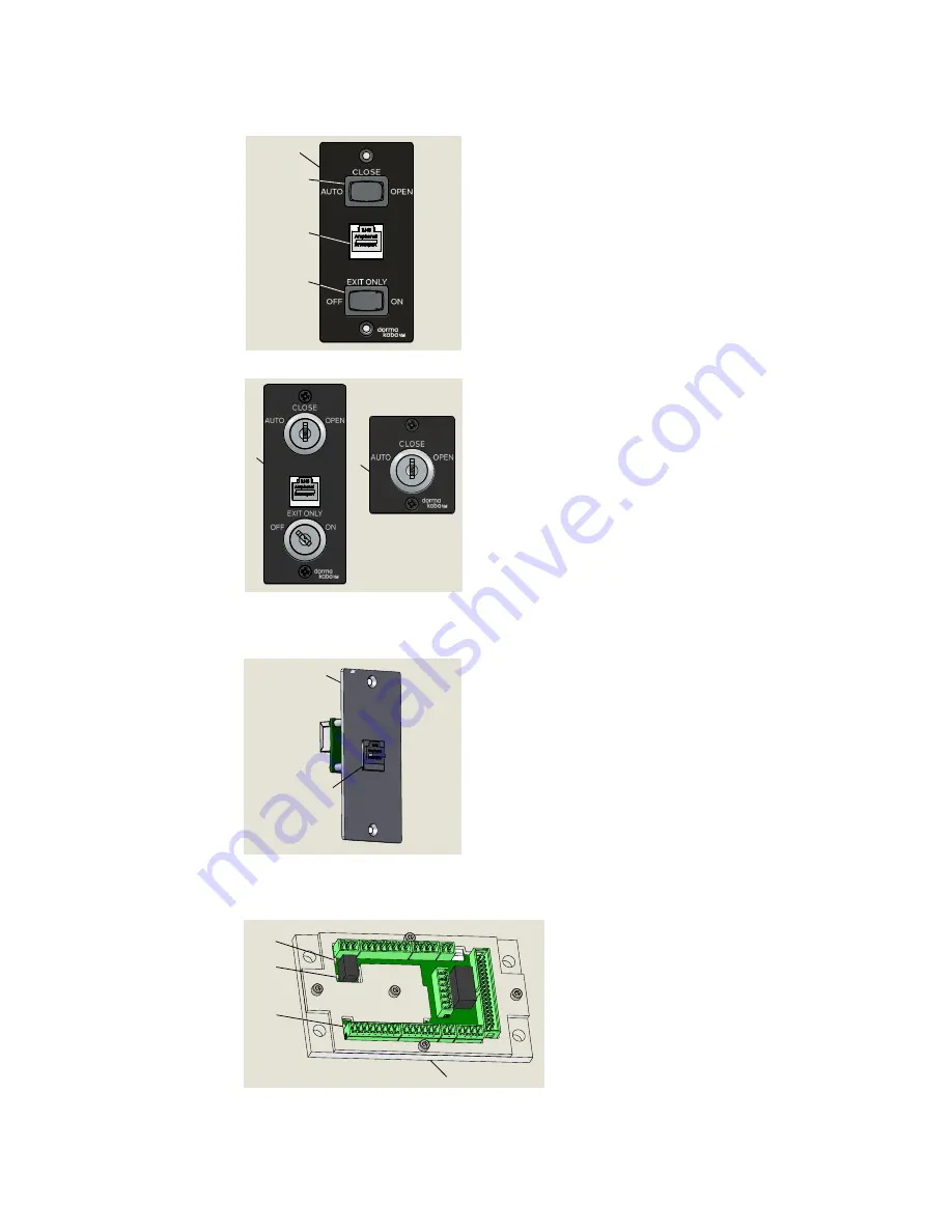
10.3 Program switch panel, optional key switch panels
Fig. 10.3.1 Program switch panel
1
Program switch
panel
1.1
Program switch,
3 position
1.3
Exit Only switch,
2 position
1.2
Comm port for
Dorma Handheld
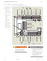
10.5 Operator status LEDs
Fig. 10.5.1 Operator status LEDs
10.5.1 Operator status LEDs
Header cover must be opened to view LEDs
located on accessory wiring terminal board.
1. Red LED
Blinking codes are used to indicate "ln__"
information (system status or operating
conditions) or certain error codes "E__".
2. Yellow LED
Maintenance interval indicator. When
illuminated, an indication the operator
system has to be serviced.
3. Green LED
• On, internal 24 Vdc power is On.
• Off, internal 24 Vdc power is Off.
1
Red LED
2
Yellow LED
3
Green LED
4
PCB assembly
5
Accessory terminal
board
10.3.1 Program switch control modes
• Auto, door opens automatically when one of the
activators is actuated or triggered and closes on
expiration of adjustable hold open time with no
activators or actuators triggered.
• Close, door closes automatically, or remains closed
until program switch position changed.
• Open, door opens automatically and remains open
until program switch position changed.
10.3.2 Exit only switch modes
• Off, Interior and exterior activation sensors both
active.
• On, exterior activation sensor disabled when door
fully closed. Only interior activation sensor will enable
door opening.
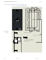
10.4 RJ45 panel
Fig. 10.4.1 RJ45 panel
10.4.1 RJ45 panel
• Supplied on double door installations.
• RJ45 cable connects panel to second ED50 operator
in header for dormakaba handheld connection.
1.2
2
1.2
Comm port for
dormakaba
handheld
2
RJ45 panel
1
1.1
1.2
1.3
5
3
2
1
2
9
Fig. 10.3.2 Key switch panels
2
Key switch panel,
RJ45, DX4604-21C
9
Key switch panel
DX4604-11C
Details on LED status codes and
maintenance intervals can be found in
Appendix C, Troubleshooting.

