40
ED50
08-2018
DL4614-140
dormakaba ED50 OHC Installation Instructions
Chapter 17
17.6 Install panic breakout, inswing doors
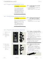
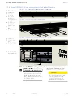
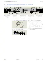
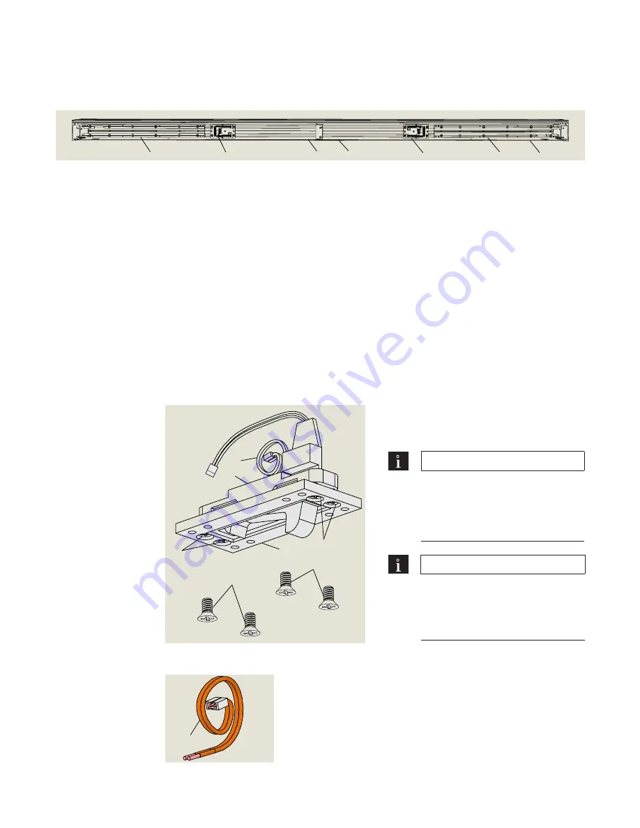
Fig. 17.6.1 Panic breakout switch kit DK4638
1
Panic breakout
switch
2
Breakout mounting
plate
3
Wire harness, 24"
long
4
#8 x 5/8" FH thread
forming screw
5
1/4-20 x 1/2" Phillips
flat head (undercut)
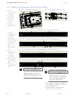
17.6.1 Install panic breakout assembly in
header.
1. Install panic breakout switch assembly in
header.
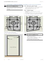
TIPS AND RECOMMENDATIONS
Wire harness (3) connects
breakout switch to ED50 terminal
board.
• Reference Chapter 35,
Connect Accessory Wiring.
TIPS AND RECOMMENDATIONS
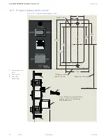
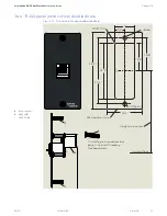
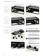
Header is shipped with cutout and
mounting holes for panic breakout
switch. Reference Figures 17.6.3
and 17.6.4.
1
2
3
4
4
5
5
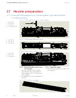
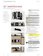
Fig. 17.6.2 Wire harness,
24" long
3
Wire harness, 24"
long
3
1
ED50 OHC double
header, outswing
shown
2
Mounting plate, LH
ED50 OHC operator
3
Terminal PC board
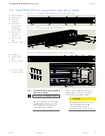
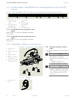
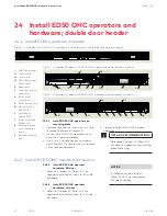
17.5 Double header: Install ED50 OHC mounting plates and Terminal PC
boards
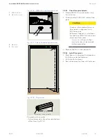
Fig. 17.5.1 OHC double header, ED50 OHC operator mounting plate and Terminal PC boards, both sides
2
3
4
5
6
6
1
module, LH ED50
operator
4
Terminal PC board
module, RH ED50
operator
5
Mounting plate, RH
17.5.1 Install ED50 OHC mounting plate left side of
header.
Refer to Para. 17.3 for mounting plate installation
instructions.
17.5.2 Install ED50 OHC mounting plate right side of
header.
Refer to Para. 17.2 for mounting plate installation
instructions.

