42
ED50
08-2018
DL4614-140
dormakaba ED50 OHC Installation Instructions
Chapter 19
19.1 Header installation
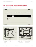
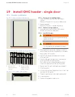
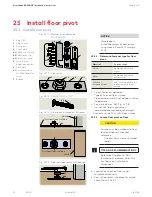
Fig. 19.1.1 Jambs installed in door opening
19 Install OHC header - single door
19.1.1 Review prior to installing header.
1. Jamb installation and floor level and flatness
verified.
• Reference Chapter 16, Customer Installed Jambs.
2. Header prepared.
• Reference Chapter 17, Header Preparation.
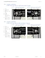
19.1.2 Header mounting hardware.
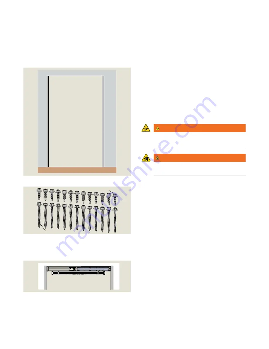
1. Hardware mounting kit DK4654-010 contains
fasteners for metal or wood jambs.
19.1.3 Install OHC header.
WARNING
Hand pinch point and crushing hazards during
header installation!
WARNING
Crushing hazards during header installation!
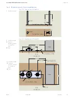
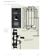
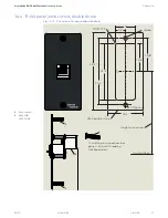
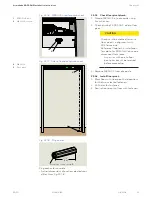
1. Place header between jambs, feeding wiring from
jambs through jamb mounting brackets into header.
• Refer to Para. 19.2 and 19.3.
2. Align left side header jamb bracket with jamb
mounting holes.
3. Install one flanged hex head screws through jamb
mounting bracket into jamb material.
• Use socket wrench to thread flanged hex head
screws into jamb material. Do not fully tighten.
4. Repeat step 3 for right side header jamb bracket.
5. Check jamb level.
6. Install remaining three flanged hex screws in left side
jamb, do not fully tighten.
7. Repeat step 6 for right side header jamb bracket.
8. Check jamb level.
9. Tighten all flanged hex head screws.
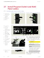
Fig. 19.1.2 Screw pack, header mounting, DK4654-010
1
#14-10 x 2 1/2"
Phillips flanged hex
head, zinc
1
2
2
1/4-14 x 1" Phillips
flanged hex head,
drilling screw, zinc
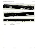
Fig. 19.1.3 OHC header;, checking level

