48
ED50
08-2018
DL4614-140
dormakaba ED50 OHC Installation Instructions
Chapter 23
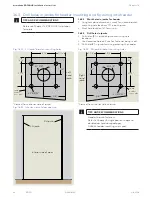
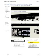
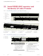
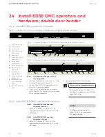
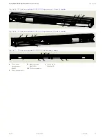
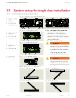
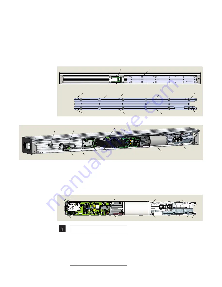
Fig.23.1.1 Header with ED50 OHC mounting plate and low voltage terminal module
1
ED50 OHC
mounting plate,
right side of header
orientation
2
Mounting holes for
operator
3
Low voltage terminal
module
23 Install ED50 OHC operator and
hardware; RH side of header
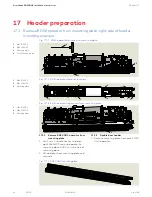
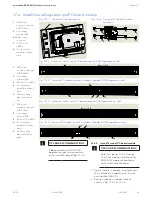
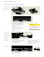
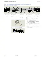
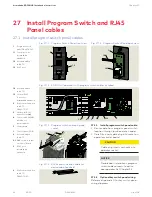
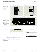
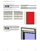
Fig.23.1.2 Header with ED50 OHC operator and hardware installed
2
2
2
2
2
2
2
2
1
3
1
1
ED50 OHC operator
1.1
Control board
1.2
Output shaft
1
2
3
4
5
5.1
6
1.1
1.3
1.2
1.3
ED50 OHC operator
115 VAC cable
2
Ribbon cable
3
Low voltage terminal
board module
4
115 Vac power
extension cable DX4647
5
115 Vac power module
5.1
Main power cable
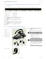
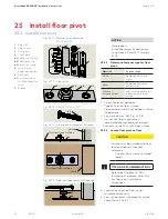
23.1 Install ED50 operator in RH side of header
DK3772-010
6
Ground lug kit
DK4556-010
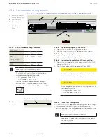
1
M6 x 10 SHCS
2
M6 x 20 SHCS
3
Mounting plate
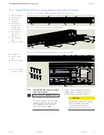
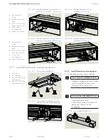
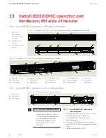
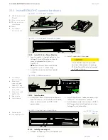
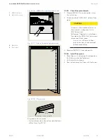
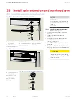
Fig. 23.2.1 ED50 operator fastener locations
1
1
1
1
2
2
2
2 3
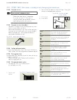
23.2.1 Install ED50 OHC operator on
mounting plate.
1. Operator protective film strips must be
removed! Reference Chapter 21.
2. Install ED50 OHC operator onto
mounting plate.
3. Use 5 mm T handle hex key to thread
eight M6 SHCS into their mounting plate
holes.
4. Tighten all eight M6 SHCS.
23.2 Install ED50 operator on mounting plate
TIPS AND RECOMMENDATIONS
• Reference Chapter 17, Para.
17.1 for detail on operator to
mounting plate fastening.
• Reference Chapter 21 for
operator bottom view of
fasteners.

