49
ED50
08-2018
DL4614-140
dormakaba ED50 OHC Installation Instructions
Chapter 23
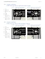
23.3 Install ED50 OHC operator hardware
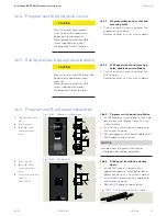
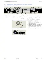
23.3.3 Install ground lug kit.
1. Thread self tapping screw into header slot.
2
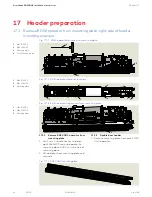
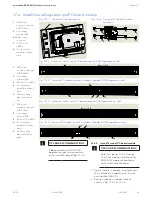
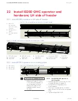
Fig. 23.3.1 115 Vac power module
2
PCB holder assembly
DC4630
2.1
Power off/on switch
2.2
115 Vac connection
circuit board
2.3
Velcro
3
Low voltage
terminal module
2
2.1
2.3
2.2
2
2.3
3
Fig. 23.3.2 115 Vac power module installed
2
3
4
5
6
7
8
Fig. 23.3.3 Cable connections
9
Ground lug kit
9.1
Self tapping screw
Fig. 23.3.5 Ground
lug kit
Fig. 23.3.4 Ground lug kit installation
3
Low voltage
terminal module
4
Main power
extension cable
DX4647, 12" long
5
ED50 OHC operator
power cable
6
Main power cable
DK3772-010
7
Ribbon cable
8
Control board
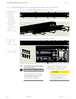
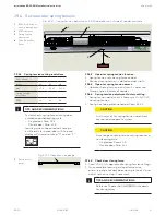
23.3.1 Install 115 Vac Power Module.
1. Locate module in header between Low
Voltage Terminal Module and jamb
mounting bracket as shown in
Fig. 23.3.2.
Note:
Main Power Extension Cable
(Fig. 23.3.3) is 12" inches long.
2. Install Velcro pad on bottom header
surface.
3. Install module on Velcro pad.
CAUTION
Insure header mounting surface
has been cleaned prior to placing
115 Vac Power Module Velcro pad
on header surface.
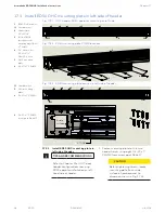
23.3.2 Install cables.
1.
Install Main Power Extension cable; one
end into socket in 115 Vac power module,
other end into socket on ED50 OHC
power cable.
2. Install Main Power Cable connector into
socket on 115 Vac power module.
3. Install ribbon cable into sockets in ED50
OHC operator control board and in Low
Voltage Terminal module.
9
9.1
9.1
9

