56
ED50
08-2018
DL4614-140
dormakaba ED50 OHC Installation Instructions
Chapter 27
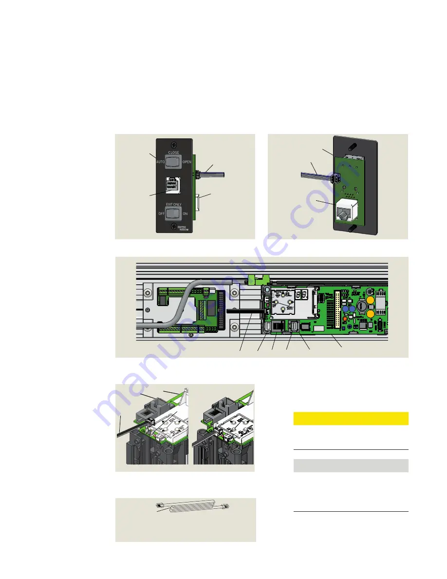
27.1 Install program switch panel cables
27 Install Program Switch and RJ45
Panel cables
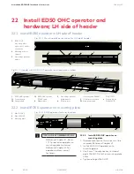
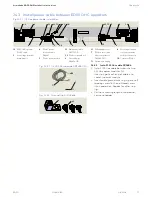
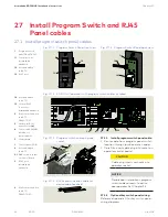
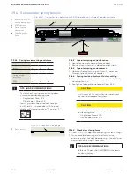
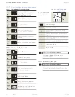
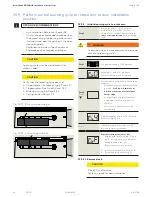
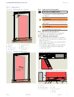
Fig. 27.1.2 ED50 OHC operator with program switch cables installed
1
Program switch
panel DX4604-02C
1.1
Comm port for
dormakaba
handheld
1.2
4 strand ribbon
cable, 10'
1.3
RJ45 port
1
1.1
1.2
1.3
Fig. 27.1.1 Program Switch Panel front view
1.2
1.3
1
Fig. 27.1.5 Program Switch Panel back view
Fig. 27.1.3 Program switch cable plug and
socket
1.2
2
3
1.3
4
5
3
2
1
2.1
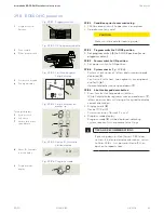
27.1.1 Install program switch panel cable.
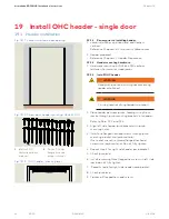
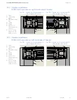
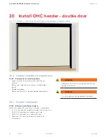
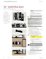
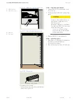
1. Route cable from program panel switch
location through jamb and into header
.
2. Carefully insert cable plug into socket on
operator control board.
CAUTION
Cable plug inserts vertically into
operator socket.
NOTICE
Double door installations, program
switch cable connects to active
door operator; Ref. Chapter 33.
27.1.2 Optional key switch panel wiring.
Reference Appendix D for key switch panel
wiring diagrams.
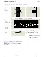
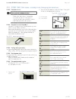
1.2
4 strand ribbon
cable, 10'
1.3
Vertical RJ45
connector,
dormakaba handheld
2
RJ45 communication
cable, 10'
DX4607-020
3
Horizontal RJ 45
connector for
(4)
4
Comm cable, DX3485
double door
synchronization
5
Control board
1
Control panel PCB
2
4 strand ribbon
cable, 10'
2.1
Ribbon cable socket
on control board
3
RJ45 port,
dormakaba
handheld
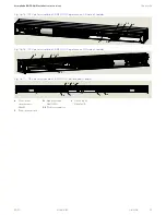
2
2
RJ45 communication
cable, 10'
DX4607-020
Fig. 27.1.4 RJ45 communication cable for
dormakaba handheld

