44
ED50LE
09-2021
DL4616-002
dormakaba ED50LE operator – Fine cover
Installation Instructions
Appendix A
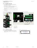
A1.6 Install Mode switch cable.
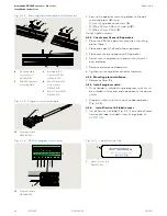
1. Insert Mode switch plug (part of HX3482-010
assembly) into connector..
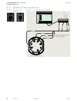
2. Route Mode switch cable to ED900 Mode switch
terminals on terminal interface board.
• Secure cable to mounting plate channels using wire
retainers.
3. Terminate cable wires at terminal strip X1 as shown
in Fig. A1.10.
Fig. A1.9 Mode switch wiring
4
4 pin plug and 4
conductor cable
assembly (part of
HX3482-010)
1
Black
Re
d
Whit
e
Gr
een
4 cond. 22 AWG
4
Fig. A1.10 Mode switch wiring at ED50LE terminal board
30
31
32
34
33
3
35
3
30
31
32
34
33
3
35
3
Black
Red
White
Green
4 Cond. 22 AWG
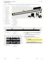
A.1.7 Install Service Call label.
1. Install Service Call label at convenient location.
Service call label included in Low Energy label kit
HK3137-010.
1
Fig. A.1.11 Label, service call


