43
ED900
02-2020
08125330
dormakaba ED900 Installation Instructions – Double egress door
Chapter 14
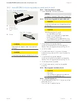
Fig. 14.1.3 Mounting plate removal
Fig. 14.1.4 5 mm T-handle
hex key
4
Guide pin
4
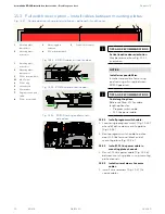
14.2 Mounting plate 115 Vac terminal blocks
1
M3 x 5 screw
2
115 Vac terminal
block
3
Spacer
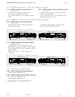
Fig. 14.2.2 115 Vac terminal block assembly
1
2
3
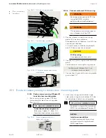
14.2.1 ED900 installation with standard
covers
(Fig. 14.2.1)
1. Customer 115 Vac is connected to
terminal block and ground stud on each
ED900 mounting plate.
Fig. 14.2.1 ED900 mounting plates – installation with standard covers
1
3
2
3
4
4
5
5
5
5
5
5
1
Inactive door
mounting plate
2
Active door
mounting plate
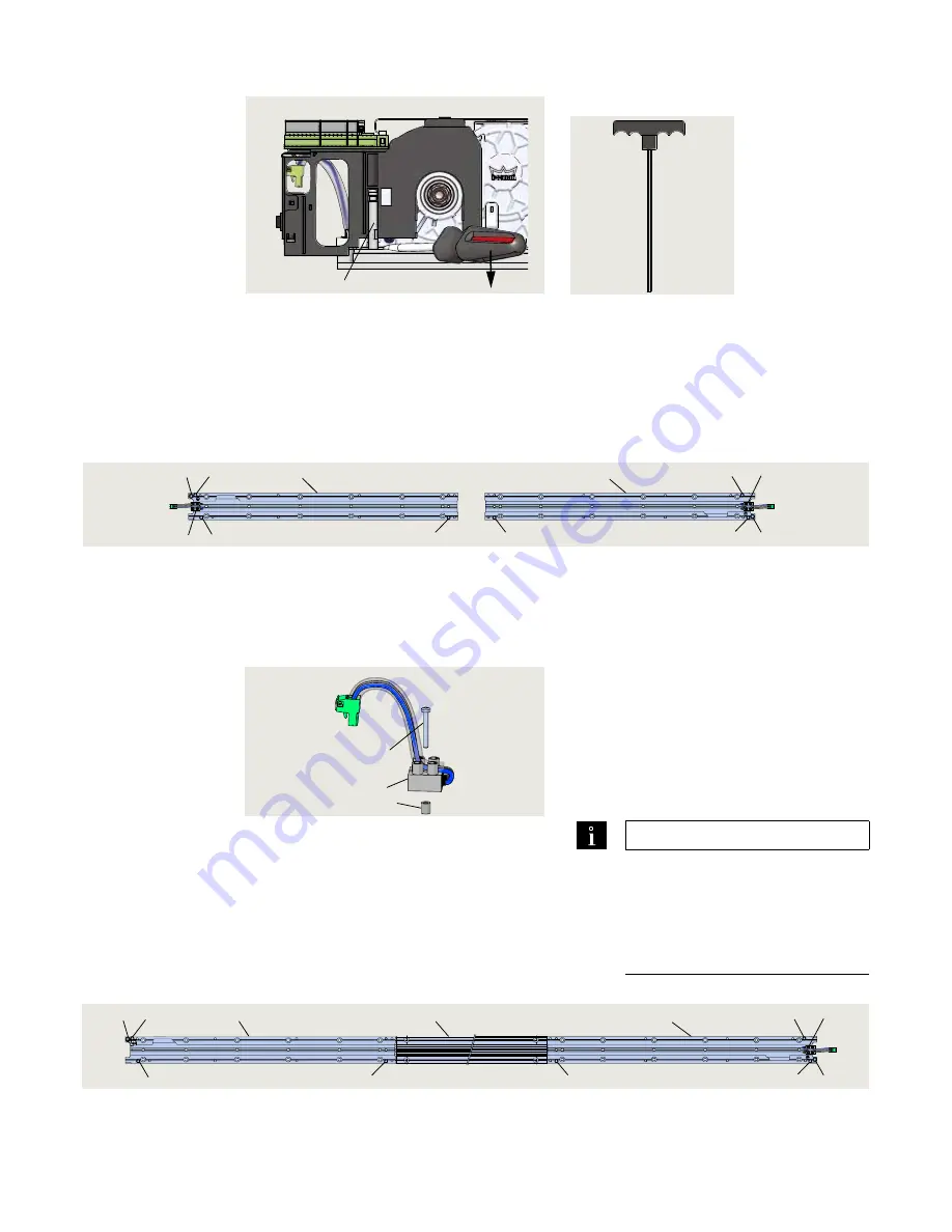
14.2.2 ED900 installation with full width
cover option
(Fig. 14.2.2)
1. Customer 115 Vac is connected to
inactive door terminal block and ground
stud.
14.2.2 Remove 115 Vac terminal block on
inactive door mounting plate.
1. Remove M3 x 5 screw securing 115 Vac
terminal block assembly to mounting
plate.
2.
Remove 115 Vac terminal block assembly.
TIPS AND RECOMMENDATIONS
Removing 115 Vac terminal block
on inactive door mounting plate is
optional.
• Wiring between mounting
plates is facilitated by
removing terminal block.
Fig. 14.2.3 ED900 mounting plates – installation with optional full width cover example
1
Inactive door
mounting plate
2
Active door
mounting plate
1
2
3
4
4
5
5
5
5
5
5
6
3
115 VAC terminal
block
4
Ground terminal
3
115 VAC terminal
block
4
Ground terminal
5
Guide pin
5
Guide pin
6
Mounting plate
extension


