dormakaba Header Installation Instructions with EML310/320 and 371/372
For use with DRS Rails and Patching Fittings (4-1/8”, 4-1/2”, 6” Headers)
933903
07-2019
EML Header Shim
19
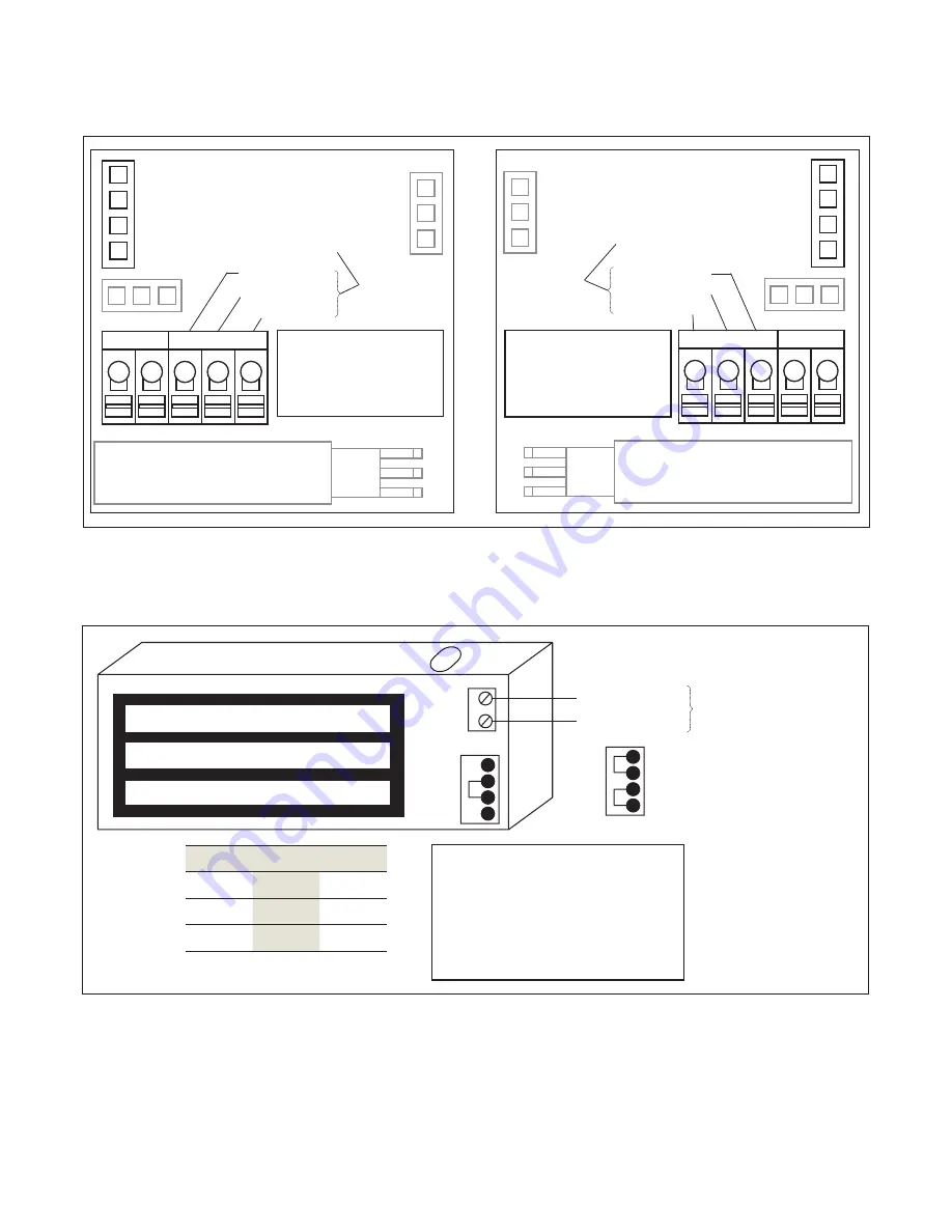
Wiring EML
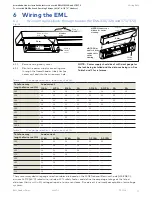
Fig. 16
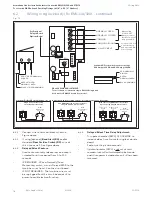
12
24
12
12
24
12
Volt
age
Jumper
s
HR
R
B
G
VDC
C
NC NO
-
Tip:
Fully depress orange tab to insert wires.
Common
Normally Closed
Normally Open
Optional BA Sensor SPDT
Output contacts rated for
maximum 1.00 Amperes at
24VDC.
LED
G
B
R
LED
G
B
R
EML371 BA and EML372 BA
Side 1
EML372 BA
Side 2
Volt
age
Jumper
s
LED
G
B
R
R
B
G
HR
-
VDC
C
NO
NC
Tip:
Fully depress orange tab to insert wires.
R
G
B
LED
Optional BA Sensor SPDT
Output contacts rated for
maximum 1.00 Amperes at
24VDC.
Common
Normally Open
Normally Closed
Fig. 17
Power input requirements
Model
12VDC
24VDC
EML371
0.52A
0.26A
EML372
1.04A
0.52A
+12/24VDC input
- (Ground)
Magnet power from
Power Supply
Jumper 12VDC
Jumper
24VDC
(preset)
Optional DP
contacts are rated
0.20A @ 12VDC and 0.12A at
24VDC
2 x BLUE LEADS Normally Open
shown with Door Open
Optional DP
contacts rated at
0.20A@12VDC and 0.12A@24VDC
2 x BLUE LEADS Normally Open
Both the BA and DP options are
shown with Door Open
Optional DP
contacts rated at
0.20A@12VDC and 0.12A@24VDC
2 x BLUE LEADS Normally Open
Both the BA and DP options are
shown with Door Open
6.3
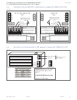
Wiring for BA or BA DP combination models (for EML371/372)
6.4
Wiring for Unmonitored or DP sensor models (for EML371/372)


