2
EML Header Shim
07-2019
933903
dormakaba Header Installation Instructions with EML310/320 and 371/372
For use with DRS Rails and Patching Fittings (4-1/8”, 4-1/2”, 6” Headers)
Table of Contents
Table of contents
1
Technical specifications
3
1.1
RTS88 and PT21 Header
Specification Overview
3
1.1.1 General information
3
1.1.2 Glass requirements/fittings/mounting 3
1.1.3 Requirements for glass panel
3
1.1.4 Safety instructions
3
1.1.5 Symbols used - Safety/Installation
3
1.1.6 Maintenance, care, repair
3
1.1.7 Disposal
3
1.2
EML310 and EML320 Specifications Overview 4
1.1.1 General information
4
1.1.2 Listings
4
1.1.3 Conditions of acceptability
4
1.1.4 EML310/320 Mechanical specifications:
(Including 1/4” [6.4] mounting bracket)
4
1.1.5 EML371/372 Mechanical specifications:
(Including 3/16” [4.8] mounting bracket)
5
1.1.6 Environmental specifications:
5
1.1.7 EML310/320 Electrical specifications:
5
1.1.8 EML371/372 Electrical specifications:
5
1.1.9 Inspection and Maintenance
5
1.3
EML header options
6
1.4
Pin diameter specifications
7
2
RTS88 and PT21 installation instructions
8
2.1
Install header for single or double door: RTS88 8
2.2
Install header for single or double door: PT21 9
2.3
RTS88 adjustments
10
2.4
PT21 adjustments
10
3
EML and shim installation instructions
11
3.1
Prepare/disassemble mag lock body
and mounting plate
11
3.2
Secure header shim to frame/ceiling surface
(for 4-1/8” or 4-1/2” headers only)
11
3.3
Secure mounting bracket and mag lock to shim
(for 4-1/8” or 4-1/2” headers only)
12
3.4
Secure mounting bracket and mag lock to shim
(for 6” headers only)
13
4
Install armature plate
14
4.1
(For use with patch fittings only)
secure glass door bracket (GDB)
14
4.2
(For use with DRS rails only)
15
5
EML310/320 and 371/372 Options
16
5.1
Instant release of lock
16
5.2
Lock monitoring options - BA -
Bond Alert Sensor
16
5.3
Lock monitoring options - DP -
Door Position Sensor
16
6
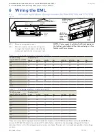
Wiring the EML
17
6.1
Wiring mag lock body through header
(for EML310/320 and 371/372)
17
6.2
Wiring mag lock body
(for EML310/320) - continued
18
6.3
Wiring for BA or BA DP combination models
(for EML371/372)
19
6.4
Wiring for Unmonitored or DP sensor models
(for EML371/372)
19
7
EML310/320 and 371/372
trouble shooting guide
20


