background image

3.  Installing the system

1

3.1 

Installing the substructure and guide rail

HSW EASY SAFE

9

The installation of the guide rail requires a horizontally (lengthwise and crosswise) aligned and bearing 
subconstruction (e. g. DORMA-UK systems). When determining this substructure you need to consider 
the fastening of the guide rail and the total weight of all panels in the stacking area. 
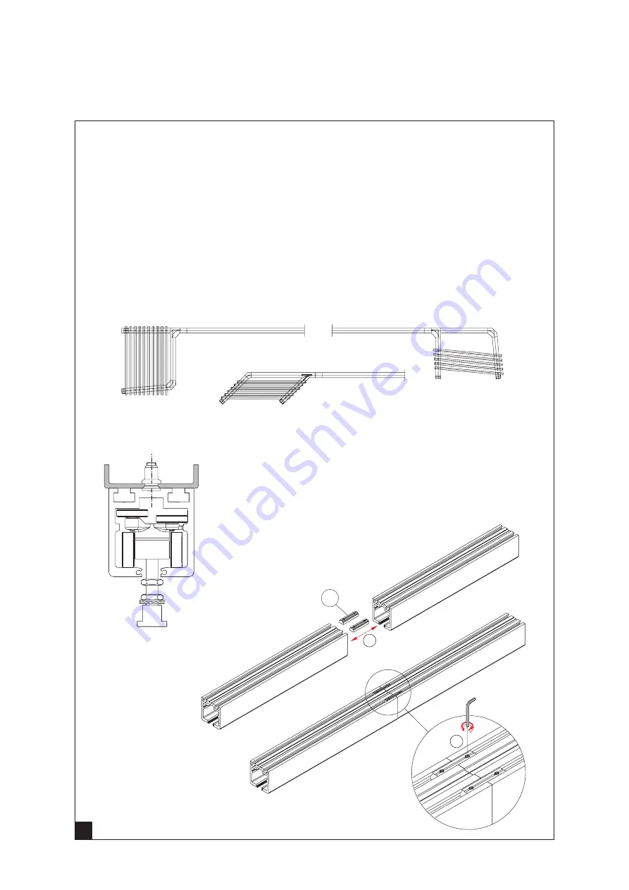
Screw the guide rail along the entire length (also in the stacking area) to the substructure.
The fastening points of the guide rail on the substructure are approx. every 300 mm on the straight line and 
approx. every 100 mm in the stacking area. 
 

Please note:


Provide all profile joints (except for the revision piece, „3.10 Installing or disassembling the revision piece“) with the clamp-
ing pieces (a) incl. the pins in order to ensure a proper run through alignment.

a

3 mm

1

2

Summary of Contents for HSW EASY SAFE

Page 1: ...Installation instructions HSW EASY SAFE WN 058735 45532 2019 08 13698 EN ...

Page 2: ...ottom rail 12 3 5 Mounting the fixed panel holders 13 3 6 Mounting the fixed panel holders 14 3 7 Preparing the upper swivel 16 3 8 Installing the upper swivel 16 3 9 Installing the single action end panel 18 3 10 Installing or disassembling the revision piece 19 3 11 Attaching the sliding panel 20 3 12 Aligning the panels in the stacking area 21 3 13 Aligning the panels in the front area 21 3 15 ...

Page 3: ...ined especially for the installation of glass 2 Glasses with chonchoidal fractures and or damaged edges may not be installed 3 There is a risk of getting pinched among other things in the area of the secondary closing edge as well as a risk of injuries due to glass breaking during the installation Wear the required protective clothing especially gloves and safety goggles 4 Prior to the final insta...

Page 4: ...alled in the support profile so that the rotation and swinging functions are possible This installation manual shows the installation in the support profile The installation in the door rail is identical Please note other enclosed installation and operating manuals Installation in the door rail Single action panel end panel sliding panel fixed panel Installation in support profile Single action sl...

Page 5: ... the ground can only be achieved with this axis 2 2 Floor concealed door closer and floor bearing 65 BTS 75 291 BTS 80 341 BTS 84 306 BTS 75 50 BTS 80 60 BTS 84 40 BTS 75 51 57 BTS 80 51 57 BTS 84 51 58 10 BTS 75 78 BTS 80 78 BTS 84 108 Floor bearing The 5 mm can be corrected by adjusting the floor bearing a Loosen the fastening screws b move the floor bearing and retighten the screws In order to ...

Page 6: ...ushings are used as the standard design with plastic inner sleeve Drill the 8 mm boreholes for the wall plug and also in the center the borehole for the eccentric bushing ø25 mm min 30 mm deep and at a distance of 65 mm to the outer edge of the door ø25 30 Insert the eccentric bushing in the continuous pipe min 15 Locking plate Eccentric bushing Borehole ø 25 mm 30 mm deep for the eccentric bushin...

Page 7: ...he 135 station areas Install one high guiding roller on the right and one high guiding roller on the left for each leaf Roller running straight through high guide rollers a left Roler in bend high guide rollers a right a a Standard stacking area 1 Parking position at right angles to the running direction 90 Standard stacking area 2 Parking position parallel to the running direction 90 Standard sta...

Page 8: ...nel SP 2 Sliding panel SP to sliding panel SP 3 Double action sliding panel DASP single action sliding panel SASP to double action sliding panel with ITS 96 DASP ITS 96 4 Sliding panel SF to single action sliding panel SASP 1 2 3 4 SAEP SP SP SP DASP SASP DASP ITS 96 SASP SP 6 HSW EASY SAFE 8 ...

Page 9: ...and the total weight of all panels in the stacking area Screw the guide rail along the entire length also in the stacking area to the substructure The fastening points of the guide rail on the substructure are approx every 300 mm on the straight line and approx every 100 mm in the stacking area Please note Provide all profile joints except for the revision piece 3 10 Installing or disassembling th...

Page 10: ...ther Slide the door rail on the glass and align it at a distance of 4 5 mm on both sides 1 Now tighten the screws so that the rail is tightly clamped to the glass socket wrench 5 mm tightening torque 15 Nm 3 2 Installing door rails on the glass panel 0 5 4 5 4 5 5 mm 15 Nm 2 1 1 ...

Page 11: ...in the door rail have been pre manufactured They are to the right and left on the face side on the inner side of the panel Install the door rail according to the general instructions see chapter 3 2 Inject the glue through the filling hole As soon as the glue exits the outlet duct the glue chamber is completely filled Remove the excess glue The glue needs 10 minutes to harden The panel can then be...

Page 12: ...e delivery mount the bottom rail to the floor Align the bottom rail according to the system drawing Mark the boreholes and and drill the holes Fasten the bottom rail with screws and dowels to the floor Please note The mounting material must be suitable for the fabric of the building ...

Page 13: ...lders Loosen the nut of the fixed panel holder with a 17 mm wrench 1 Slide the support block into the door rail or the support profile 2 Position the support block at a distance of 60 5 mm from the outer edge 3 Slightly tighten the nut 4 60 5 1 1 2 3 4 ...

Page 14: ...nt the bottom rail to the floor The fixed panel has holders instead of the roller carriers Turn the head of the fixed panel holder by 90 1 so that the panel with the holder can be inserted into the guide rail 2 2 3 Insert the fixed panel holders at the top into the guide rail 2 Place the panel at the bottom rail 3 1 ...

Page 15: ...uide rail 2 Turn the head of the fixed panel holder by 90 3 so that the holder can be engages into the guide rail Secure the position of the fixed panel holder using the threaded pin 4 Secure the height of the panel with the nut 5 Screw the fixed panel with the bottom rail to the floor 6 90 3 mm 17 mm 7 mm 15 mm flush 17 mm 1 2 3 4 5 6 6 ...

Page 16: ...ce 3 8 Installing the upper swivel Press the retaining washer together using a gripper and insert it into the pin channels of the guide rail Insert the upper swivel into the guide rail position it at a distance of 70 mm pivot point towards the wall and fix it using the threaded pins 5 mm socket wrench 70 5 mm 1 2 1 2 3 ...

Page 17: ...panel Loosen the nut with a 17 mm wrench 4 and then turn the bolt downward using a 8 mm wrench 5 Insert the supporting block into the door rail or the support profile and position it at a distance of 60 5 mm from the outer edge Now secure the nut again 17 mm 8 mm 60 5 4 5 6 7 ...

Page 18: ...e of the guide rail 4 Now slide the retaining washer forcefully over the bolt 5 8 mm Screwing in HSW EASY SAFE 18 3 9 Installing the single action end panel 70 65 5 Install the panel 1 by inserting the bolt into the upper swivel 2 and by subsequently placing it on the floor bearing 3 1 2 3 4 5 ...

Page 19: ...piece The revision piece can be disassembled during the replacement of defective rollers Drive the tapered dowel pins out of the revision piece and unscrew the screw The revision piece must always be screwed in place again 6 mm Tapered dowel pin Tapered dowel pin 1 2 ...

Page 20: ...blocks on the floor and insert the attachment blocks on the left and right into the support profile d Aligning the panel height Align the panel so that there is a 12 mm gap at the bottom without cover profiles between the floor and the base profile Loosen the nut for the height adjustment c Adjust the height via the nut b 17 mm wrench Turning left more play at the bottom Turning right less play at...

Page 21: ...nels in the stacking area Slide the attached panel into the stacking area and align the panel laterally to the first panel Carefully move the panel The rollers are not fixed at this point so that they will assume the correct distance in the stacking area If necessary loosen the nut c Align the panel in the stacking area Retighten the nut c once the alignment has been completed c 1 2 3 3 Lateral al...

Page 22: ... the sleeve onto the axis Now install the cover plate as follows Insert the rubber seal along the entire length into the cover profile Place the cover profile against the door rail at the bottom and carefully clip it onto the door rail using a protective piece and a hammer Pull the sleeve and unlock the panel so that the sleeve rests against the cover plate Now insert the front locking bolt straig...

Page 23: ...refully clip it to the door rail using a protective piece and a hammer Intermediate layer 19 3 17 Installing the brush profiles Insert the brush profile into the carrier profile and align it in height Fix brush profile with a plastic wedge from left and right Press the separated plugs for sealing into the carrier profile at each side 18 1 2 3 1 2 4 21 4 21 5 6 7 HSW EASY SAFE 23 ...

Page 24: ...ons with the combi fixing block see chapter 2 6 3 18 Installing the face covers Insert the plastic cap on the face cover and fix the entire face cover using the screw on the door rail 1 2 1 2 3 3 19 Installing the combi fixing block HSW EASY SAFE 24 ...

Page 25: ...HSW EASY SAFE 25 22 3 20 Installing the upper locking device Position fix and wedge the panel 5 mm Slightly tighten 8 mm Turn the hook upwards 5 mm Fasten 1 1 2 3 4 5 6 ...

Page 26: ...ottom with the guide rail If a door closer is provided on the single action end panel the door rail or the support profile has been prepared Mounting the spacer plate to the door rail or the support profile 1 Make sure that the slotted holes are in the upper area of the spacer plate 2 Drill the guide rail according to the provided drill pattern 2x M5 3 Do not use the enclosed drilling template of ...

Page 27: ...k et wrench The ITS 96 can now be adjusted 2 mm in the zero position Press the ITS in the direction of the offset side and fix the screw afterwards For more adjustments of the closer please follow the instructions in the installation manual 1 2 3 4 3 mm 2 mm 1 The opening limiters of door closers must not be used as door stops Use a doorstop HSW EASY SAFE 27 ...

Page 28: ...950 Translation of the original document subject to change without notice www dormakaba com 6 Removing the cover profile ATTENTION Risk of property damages due to incorrect procedure Do not use a screwdriver or similar Remove the cover profile from the door rail with a glazing shovel item no 81640200099 ...

Reviews: