Page 3
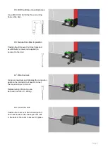
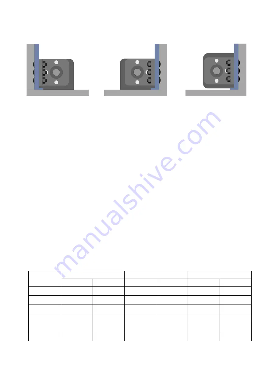
Lock fitted to the floor, strike
bolted to the door on the left.
Lock fitted to the floor, strike
bolted to the door on the right.
Lock mounted to the wall, strike
bolted to the door on the right.
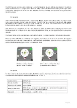
There are three magnets in the strike which offers the flexibility of mounting options and with the symmetrical design
of the lock, the strike can approach from either the right, left or bottom face of the lock as shown below.
3.2 Electrical
After the positions of the lock and strike are determined, establish where to run the wires and also decide on what
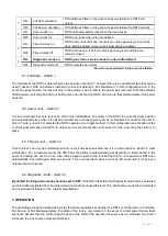
feedback is required from the lock. There are a total of eleven available connections on the lock; three are compulsory
and eight are optional.
The three essential connections are; Positive (+), Negative (-) and Control (CL). There need to be wires run from the
power source and control switch to the lock.
The eight optional connections all provide feedback about the locks state; Door Position, Bolt Locked Position and
Bolt Unlocked Position. If desired, wires can be run from these connections to integrate into access control or alarm
systems to provide full monitoring.
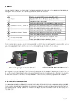
Once the number of wires and their destination is determined, it needs to be decided how the wires will enter the
lock. They can either come in though a 20mm wiring gland at the rear of the lock
(not supplied),
or through a hole
under the locks base which will ensure the wires can be hidden in the floor or wall.
Finally, the correct wire gauge needs to be chosen to ensure a minimal voltage drop. The correct wire gauge is
important when connecting the power wires (+ and -) to the lock as voltage drop across these wires can limit the
locks operation and prematurely deplete the batteries. For all the remaining connections, a lower gauge wire can be
used as these are only signal wires.
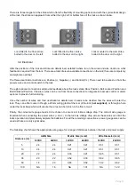
The following chart shows the appropriate wire gauge for a range of distances between the lock and power supply.
Distance (m)
AWG Size
Metric Size (mm2)
Wire Diameter (mm)
12VDC
24VDC
12VDC
24VDC
12VDC
24VDC
5
24
24
0.21
0.21
0.51
0.51
10
24
24
0.21
0.21
0.51
0.51
20
22
24
0.33
0.21
0.65
0.51
30
20
22
0.52
0.33
0.82
0.65
50
18
20
0.83
0.52
1.02
0.82
100
NA
16
NA
1.31
NA
1.29


