background image


             Page 7 


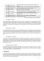
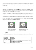
ON 

Fail Safe operation 

With batteries fitted, in the event of a power failure the RD10 will 
unlock  

OFF 

Fail Secure operation 

With batteries fitted, in the event of a power failure the RD10 will lock  

ON 

Auto re-lock on 

RD10 will automatically lock when the door closes 

OFF 

Auto re-lock off 

RD10 only locks when the user desires 

ON 

Timed re-lock on 

RD10 will re-lock after one minute if an unlock signal is given and the 
door remains closed - Auto re-lock must also be enabled  

OFF 

Timed relock off 

RD10 will never re-lock if an unlock signal is given and the door 
remains closed 

ON 

Diagnostic mode on 

RD10 goes into a service mode to output information* 

OFF 

Diagnostic mode off 

RD10 operates as normal   

            *Should only be activated in the event of a failure. 


6.1 Fail State 

– 

Switch 1 


The fail state of the RD10 is determined by the selection of switch 1; however there is an additional state that can be 
used  if  desired. With no  batteries  installed  the  lock will  default  to Fail  Maintained.  In this  configuration  and  in  the 
event of a power failure, the lock will stay in the position it was in before the power was removed. With the batteries 
fitted however, selecting Fail Safe or Fail Secure ensures that the RD10 will move to that selected state if the power 
does fail. 


6.2 Auto re-lock 

– 

Switch 2 


It is recommended that Auto re-lock be ON in most installations. The ability of the RD10 to sense the doors position 
and automatically lock when it is closed is paramount to increasing security as it eliminates the need for the user to 
do so. If Auto re-lock is not selected the RD10 operates on a toggle method. In this configuration an activation of the 
control signal will cause the RD10 to unlock and a second activation will cause it to lock, assuming the strike is in 
place. 


6.3 Timed re-lock 

– 

Switch 3 


Timed re-lock can only be enabled when Auto re-lock has been selected and it is recommended to be ON in most 
installations. For increased security the RD10 has the ability to automatically lock itself after a timed period in the 
event of a failure of a user to do so. If an unlock signal is given to the lock but the door is not opened the RD10 can 
automatically  lock  itself  again  after  one  minute.  This  ensures  that  a  door  cannot  be  left  unsecured  if  it  has  been 
unlocked but not opened.  


6.4 Diagnostic mode 

– 

Switch 4 


By default the Diagnostic mode should be set to OFF

. If the RD10 fails then the Diagnostic mode can be activated 

and information extracted from it to help determine what has caused the fault. This information needs to be interpreted 
by a registered distributor or the original manufacturer. 


7. OPERATION  


The operating scenarios detailed below stay the same regardless of whether the RD10 is configured in a Fail Safe, 
Fail Secure or Fail Maintained state. The state of the lock is only relevant in the event of a total power failure. Both 
scenarios assume that the control signal is open at the start of the operation sequence as a maintained connection 
will cause the lock to stay unlocked indefinitely.  

Summary of Contents for RD10

Page 1: ...INSTALLATION AND OPERATING INSTRUCTION Electronic Roller Door Lock RD10 ...

Page 2: ...kes position o Drill the strikes mounting holes o Secure the strike in position o Wire the lock o Cover the lock WIRING OPERATING CONFIGURATION o Fail State o Auto re lock o Timed re lock o Diagnostic mode OPERATION o Auto re lock ON o Auto re lock OFF o General o Alarms SPECIFICATIONS DIMENSIONS o Lock o Strike MAINTENANCE WARRANTY UPGRADE 2 2 2 2 3 4 4 4 4 4 5 5 5 5 6 6 7 7 7 7 7 8 8 9 9 10 10 1...

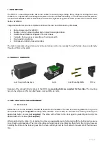
Page 3: ...nally through a 20mm wiring gland 2 PRODUCT UNBOXED Lock Cover with two keys Lock Lock Mounting Bolts Strike Because of the various fitting locations of the RD10 no mounting bolts are supplied for the strike The mounting holes in the strike are 8 5mm slotted holes so accept M8 size bolts 3 PRE INSTALLATION ASSESMENT 3 1 Mechanical Before the lock can be installed consider its location and orientat...

Page 4: ...ion If desired wires can be run from these connections to integrate into access control or alarm systems to provide full monitoring Once the number of wires and their destination is determined it needs to be decided how the wires will enter the lock They can either come in though a 20mm wiring gland at the rear of the lock not supplied or through a hole under the locks base which will ensure the w...

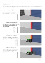
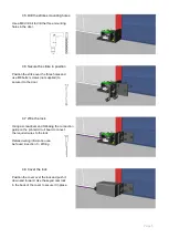
Page 5: ...ree mounting hole locations through the lock base 4 2 Drill the lock mounting holes Use a M8 masonry bit to drill the three mounting holes in the concrete floor Make the holes at least 70mm deep 4 3 Secure the lock in position With the lock positioned over the holes in the floor install the three supplied Dyna bolts and tighten them 4 4 Mark the strikes position Locate the strike in the correct po...

Page 6: ...ts screws not supplied to secure it to the door 4 7 Wire the lock Using a screwdriver and following the connection guide on the printed circuit board connect the required wires to the lock Detailed wiring information can be found in section 5 Wiring 4 8 Cover the lock Position the cover over the lock and push it down and forward Use the keyed cam lock in the back of the cover to secure it in place...

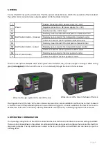
Page 7: ...or Position Switch Normally open contact of the door position monitor C Common contact of the door position monitor There are two options available when running wires into the RD10 they can be brought in through a 20mm wiring gland not supplied in the rear of the cover or run discreetly through the hole in the locks base Running wires out of the lock via the hole in base ensures a more secure inst...

Page 8: ...sition and automatically lock when it is closed is paramount to increasing security as it eliminates the need for the user to do so If Auto re lock is not selected the RD10 operates on a toggle method In this configuration an activation of the control signal will cause the RD10 to unlock and a second activation will cause it to lock assuming the strike is in place 6 3 Timed re lock Switch 3 Timed ...

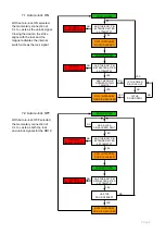
Page 9: ...NO DOOR CLOSES HAS THE DOOR OPENED UNLOCK SIGNAL HAS THE BOLT PIN RETRACTED AFTER 3 ATTEMPTS RD10 IN STANDBY DOOR IS UNLOCKED RD10 IN STANDBY DOOR IS LOCKED HAS THE BOLT PIN EXTENDED AFTER 3 ATTEMPTS HAS A LOCK SIGNAL BEEN SENT YES YES NO NO YES NO YES NO YES NO DOOR CLOSES INTERNAL ALARM SOUNDS HAS THE BOLT PIN EXTENDED AFTER 3 ATTEMPTS IS THE DOOR OPEN HAS THE DOOR OPENED WITHIN 1 MINUTE UNLOCK ...

Page 10: ...uired If the batteries are not replaced once they have become depleted the RD10 will automatically revert to the Fail Maintained state i e in the event of a power failure the lock will stay in the position it was in before the power was removed The three monitors can be used to provide door and bolt position information regardless of the locks configuration Manual operation of the RD10 is availabl...

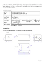
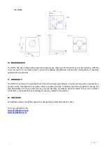
Page 11: ...he lock is free to operate as normal 8 SPECIFICATIONS Bolt Pin Stainless Steel ø18mm 35mm stroke Lock Die Cast Aluminium 152mm x 88mm x 78mm Strike Die Cast Aluminium 75mm x 75mm x 70mm Holding Force 3000Kg 30000N Power Supply 12 24VDC 15 Durability 1 000 000 Operations Current Usage Holding 12V 15mA Operation 12V 300mA Stall 12V 2A 24V 15mA 24V 200mA 24V 1A Batteries 4 x AA 1 5VDC Alkaline Monito...

Page 12: ...arranty against faulty or malfunctioning parts components or product At the manufacturer s discretion either a replacement lock or affected part will be supplied to remedy the fault Mistreatment or ill use of the lock may void the warranty dormakaba will not be liable for any direct indirect incidental or consequential loss or damage in any way related to this product 12 UPGRADE dormakaba reserves...

Reviews: