background image

24 

Saffire LX PK3704_T   02-19

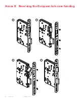
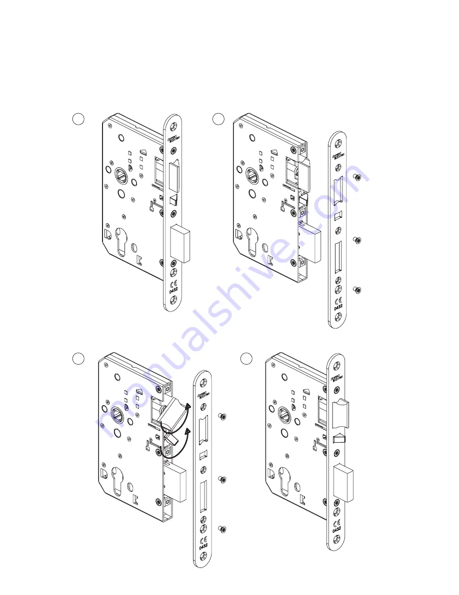
Annex B   Reversing the European lock case handing

1

3

2

4

Summary of Contents for Saffire LX

Page 1: ...Saffire LXTM Installation instructions PK3704 T 2019 02 EN ...

Page 2: ...4 25 26 Table of Contents 2019 dormakaba Canada Inc All trademarks and registered trademarks are the property of their respective owners Model Saffire LX Caution Changes or modifications to this equipment not expressly approved by the party responsible for compliance could void the user s authority to operate the equipment This device complies with part 15 of the FCC Rules Operation is subject to ...

Page 3: ...ot cause damage dormakaba standard warranty does not cover damages caused by installation Respect applicable building codes regarding handle height Definition of Terms In these instructions the term ASM refers to American Standard Mortise and ADB refers to Autodead bolt Mortise MKO refers to Mechanical Key Override Technical Assistance For technical assistance call 1 877 468 3555 1 514 735 5410 1 ...

Page 4: ...dels only 7 1 INSIDE TRIM COVER 8 1 INSIDE TRIM W ANTENNA 9 1 ANTENNA ASSEMBLY 10 1 BACK UNIT CHASSIS ASSEMBLY 11 1 INSIDE BUSHING 12 1 INSIDE LEVER BUSHING 13 1 COMPRESSION SPRING 14 1 ASM MORTISE 15 1 ASM FACE PLATE 16 1 STRIKE 17 1 DUSTBOX 18 1 TURN KNOB SPINDLE locks with turn knob only 19 1 INSIDE SPINDLE 20 1 LATCH 21 1 BACK PLATE CYLINDRICAL ASSEMBLY 22 1 KEY CYLINDER PROVIDED SEPARATELY 23...

Page 5: ...5 3 Components 3 2 European lock case EUROPEAN LOCK CASE EUROPEAN CYLINDER 23 24 25 26 ALL OPTIONS SHOWN dormakaba DeutschlandGmbH DORMA Platz 58256 Ennetpetal Germany 18 3X810G6HC20 None 0432 CPR 00026 99 EN 12209 2003 AC 2005 ...

Page 6: ...EW 12 24 X 1 5 8 IF ASM MORTISE LOCKS OR CYLINDRICAL LATCH LOCKS 3 810 515532 1 SCREW M4 X 30 MM IF EURO LOCK CASE LOCKS 2 810 514739 5 SCREW M5 X 30 MM IF EURO LOCK CASE LOCKS 2 7 017 515489 INSIDE LEVER BUSHING 1 8 025 515498 SNAP HOLDER FOR SPRING STOPPER 1 MKO ITEM NO PART NUMBER DESCRIPTION QTY 1 020 515480 1 INSIDE SPINDLE 1 2 020 515481 TURN KNOB SPINDLE 1 3 017 515483 OUTSIDE BUSHING 1 4 9...

Page 7: ...r for MKO only Insert the cylinder core in the front lock housing assembly Secure the cylinder core using screw item 11 refer to table 2 Install the access plate key cylinder item 9 refer to table 2 over the key override housing Secure the access plate using two screws item 10 refer to table 2 CAUTION WARNING IMPORTANT Access plate must be installed for proper operation of the lock 4 Installation ...

Page 8: ...humb turn hole are aligned If the holes are misaligned use a flat head screw driver to correct the position Insert the thumb turn spindle item 2 refer to table 2 into the thumb turn hole Press firmly to ensure the spindle clicks in place Rotate the spindle to ensure that the part remains in place Index markers to be aligned ...

Page 9: ...nd closing door mechanism Prior to installing the spindle you must first adjust the required positioning of the hub receiving the spindle There are 2 modes Left Hand LH and Right Hand RH according to door handing Turn the hub for correct door handing by turning clockwise for right handed and counter clockwise for left handed door entries RH VIEW LH VIEW Right RH Left LH Insert the spindle item 1 r...

Page 10: ...s not come preinstalled CAUTION WARNING IMPORTANT If the handing of the lock needs to be changed please refer to annex C for changing the handing of the cassette if the lock has a handed cassette locks with automatic dead bolt or with inside lever switch LH has arrow pointing L RH has arrow pointing R To set proper handing insert the lever from the back plate and turn in the direction required for...

Page 11: ...lder for spring stopper item 8 refer to table 2 to lock and prevent lever from disengaging CLICK TO REMOVE CLIP SQUEEZE IN TABS TO RELEASE HOOKS ENGAGEMENT 1 1 2 ALIGN SPRING STOPPER AND BACKPLATE HOLES BEFORE INSTALLING SNAP HOLDER 4 5 Step 5 Install the locking mechanism on the door Before starting the installation of the lock on the door please make sure the door has been prepared properly with...

Page 12: ...ION WARNING IMPORTANT Max 1 4 Mortise Door Door Frame Verify the mortise handing for LH or RH If the handing needs to be adjusted refer to instructions in the annex A Remove the faceplate by removing the two screws Insert the mortise in the side of the door If the mortise is equipped with a cable route the cable so it comes out of top hole on the side of the inside trim assembly Note If lock is eq...

Page 13: ...screws Install the strike and the dust box on the door frame CAUTION WARNING IMPORTANT When strike is installed on wood frames under one inch 1 thick wood screws supplied are not adequate Use screws of appropriate length to engage the structural stud behind the frame Use only the strike and dust box supplied Use of non approved parts may void the product warranty ...

Page 14: ... bolt head as per closing direction Tighten the two screws Closing Direction Verify the door thickness The lock is assembled at the factory for door thickness of 1 If the door thickness is differ ent refer to table 3 below to adjust the spacers Extra spacers and screws are provided in the hardware bag Door Thickness Spacer Spacer Screw 07 08 06 1 3 8 35mm to 1 9 16 40mm 2 3 8 10mm 1 5 8 41mm to 1 ...

Page 15: ...nding Install the cylindrical unit from the outside of the door toward the inside in order to engage the latch as illustrated below outside Cylindrical unit Latch Install the strike and the dust box on the door frame CAUTION WARNING IMPORTANT Use only the strike and strike box supplied The use of non approved parts will result in a functionality problem and may void the product warranty ASA Strike...

Page 16: ... selected Install the strike and the dust boxes on the frame of the door 4 9 Step 6 Install the lock housing on the door Install the front lock housing routing the wire cable s by the center hole at the top Install the inside housing Install the screws item 6 refer to table 2 provided and tighten Verify that the lever of the inside housing can retract the latch If not it means the lock handing is ...

Page 17: ..._T 02 19 17 4 Installation Steps 4 10 Step 7 Install the antenna module if applicable Position the bracket on the door engaged with the T at the top of the chassis Secure the bracket with screw provided with the bracket ...

Page 18: ...guide Before installing the lock on the door extend the wire guide outward without removing the cover Pull gently and rotate clockwise to lock Secure the front lock housing with the inside trim chassis using the 3 screws item 6 refer to table 2 Extend Remove the cover on the wire cover The cover will no longer be used Now that cables are exposed connect each cable with its matching connector Push ...

Page 19: ...er to a vertical position pointing up Slide the inside cover onto the lever handle taking care not to scratch the lever handle When the cover is fully in place secure it using the 3 screws item 5 refer to table 1 For locks with an ADB mortise automatic deadbolt mortise apply the privacy thumbturn sticker L H Locks R H Locks ...

Page 20: ...ry holder CAUTION WARNING IMPORTANT Use only Alkaline batteries 4 15 Step 12 Test lock functionality Make sure the room door is open prior testing A Present test keycard B Check green red lights flash C Rotate outside lever to check bolt retraction D Release outside lever should move freely back to horizontal rest position E Rotate inside lever to check bolt retraction F Release inside lever shoul...

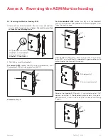
Page 21: ... using a screwdriver until the deadbolt D extends approximately 1 4 D 1 4 H Proceed to step 3 For Autodeadbolt ASM rotate hub H until the deadbolt D is fully retracted The deadbolt will extend approx 1 16 from the mortise case D 1 16 H Hold deadbolt D gently Press and release the auxiliary latch X You should feel the deadbolt trigger and begin to extend under the force of the spring D hold gently ...

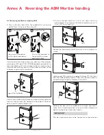
Page 22: ... small screwdriver L T S part 027 510382 Continue to hold tool S Release the latch bolt L and keep the anti friction latch F toward the flat side of the latch bolt so that the bolt extends fully L F S 4 Pull out the latch bolt L until it just clears the front plate Note If you remove the bolt completely you must turn it 90 to re insert it L 180 Rotate the latch bolt L 180 Re insert it to the end o...

Page 23: ...lar OK If the auxiliary latch X is a crescent shape remove it turn it 180 and replace it The auxiliary latch slides easily in and out of the mortise X crescent must be reversed 180 re insert 7 Assemble back screw V and lock washer W if appli cable The screw V must be tightened CAUTION WARNING IMPORTANT Screw V must not touch the back wall of mortise cut out on the door 8 The mortise should look li...

Page 24: ...24 Saffire LX PK3704_T 02 19 Annex B Reversing the European lock case handing 1 3 2 4 ...

Page 25: ...sette 1 Unscrew the screw holding the top plate of the cassette 2 Flip the top plate and reinstall on the cassette You should see now the other letter for the handing Secure the top plate with the screw The cassette is on the inside trim assembly LEFT HAND RIGHT HAND ...

Page 26: ...26 Saffire LX PK3704_T 02 19 Annex D Installing Outside Housing with Gasket ...

Page 27: ...rmakaba com dormakaba Customer services support 1 800 999 6213 1 248 837 3700 General information www dormakaba us Online consumable orders www saflokstore com To access all of our easy steps please visit our support website www dormakabalodgingsupport com ...

Reviews: