5 Parameterization
(SVA 2000/2000F only)
5.1 LED display
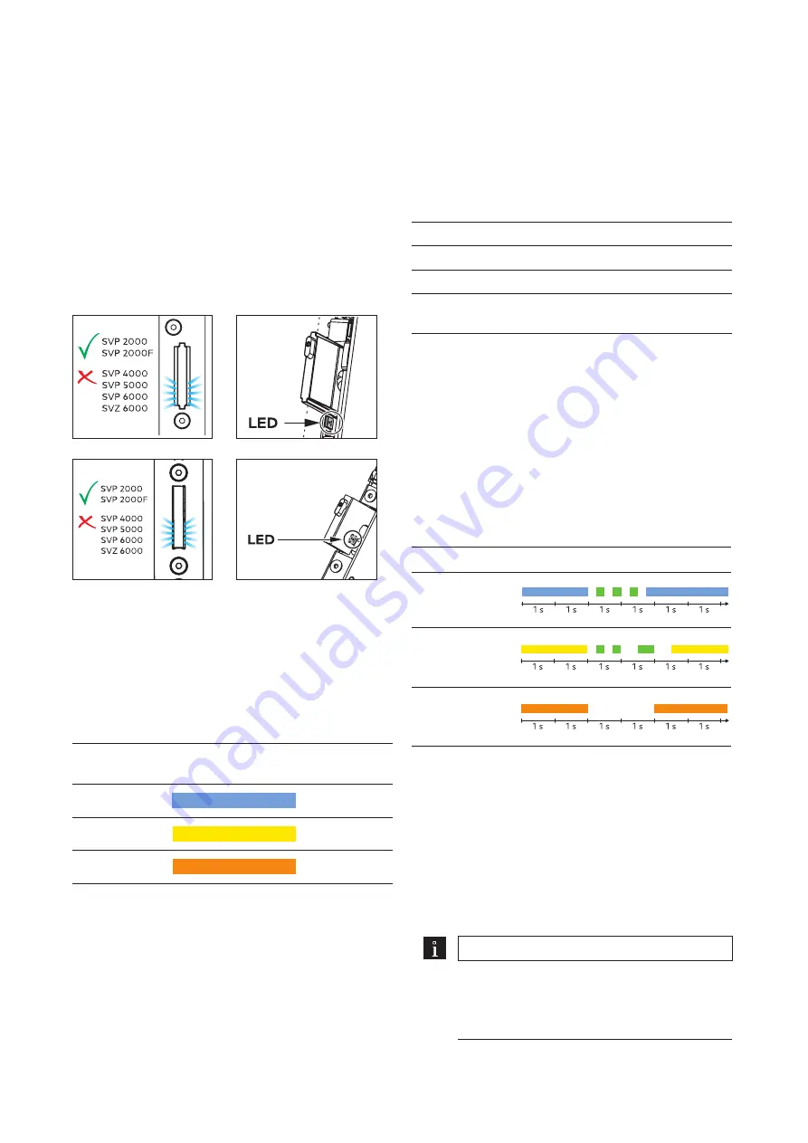
With the SVA 2000 and SVA 2000F, colored light
signals in the area around the bolt indicate the
status of the parameterizable values (Abb. 25 and
Abb. 26). The LED is covered by the forend and is not
directly visible. The LED color indicates the operation
mode when the door is open (see chapter 5.2.1).
The LED display signals the options selected during
parameterization (see chapters 5.6.1 to 5.6.3). In
addition, the LED display shows the error messages
(see chapter 9).
Fig. 25
LED display in bolt recess for tubular frame locks
Fig. 26
LED display in bolt recess for solid door locks
5.2 Adjustable parameters
5.2.1 Operation mode
The operation mode determines whether and how the
signals are transmitted between the door lock and the
control unit. During normal operation, the LED lights
up in the operation mode’s color as soon as the door is
opened.
Operation
mode
LED display
DCW® bus
blue
CAN bus
yellow
Stand Alone
orange
In DCW® bus operation, the SVA 2000/2000F can
be combined with a DCW® component, e.g. a SVP-S
4x/SVP-S 3x control unit, a SafeRoute® SCU or the
ED 100/ED 250 swing door operator. In DCW® bus or
CAN bus operation, the lock is controlled externally. In
Stand Alone operation a potential-free switch can, for
example, be connected.
5.2.2 Bus address
The components on a bus must be registered with
a unique address. SVA door locks can be assigned
addresses 1 to 4. If a door lock with address 1 is
already connected to the door, a different address
must be set on the second SVA door lock (see chapters
5.6.1 and 5.6.2).
5.2.3 Terminating resistor
In the CAN bus operation mode, the terminating
resistor must be switched on for the door lock with the
greatest distance to the bus center point.
5.3 Default settings
Parameter
Default setting
Operation mode
DCW® bus
Bus address
1
Terminating resistor
(only on CAN bus)
Switched off
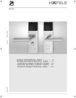
5.4 Display at system start
As soon as the operating voltage is switched on, the
LED displays the last set parameters one after the
other when the door is open:
• Operation mode: The LED lights up blue, yellow or
orange for 2 s.
• Bus address in DCW® or CAN bus operation: The
LED flashes green 1 x – 4 x.
• Terminating resistor (only in CAN bus operation):
The LED lights up green for 1 s when the resistor is
switched on. If the resistor is switched off, there is
no additional signaling.
Example
LED display at system start
DCW® bus,
Address 3
CAN bus,
Address 2,
resistor on
Stand Alone
5.5 Change parameters
5.5.1 Requirements
• The door lock is mounted (see chapter 4) and is
under operating voltage.
• The system was de-energized for min. 30 seconds
before start-up.
• The system was started up max. 20 min ago.
• The LED is not signaling an error (see chapter 9) and
indicates an operation mode (see chapter 5.2.1).
TIPS AND RECOMMENDATIONS
Read the entire procedure.
Changed parameters must be saved within
5 min, otherwise parameterization is
aborted (see chapter 5.6.5).
15
SVA door locks
2019-07
WN 059743 45532
dormakaba Mounting instructions
Parameterization (SVA 2000/2000F only)


