background image

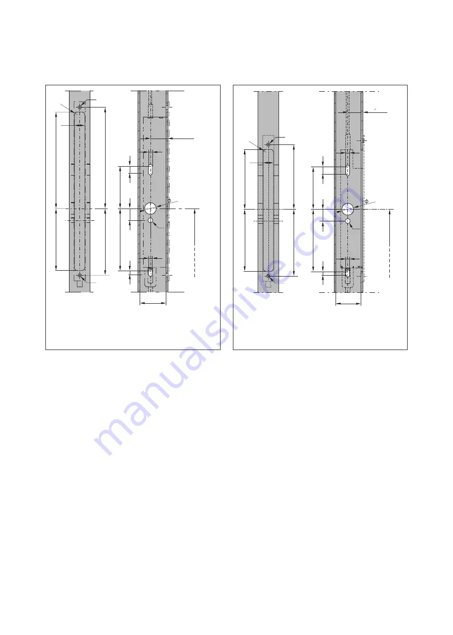
4.3  Preparatory work

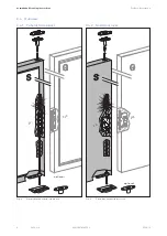
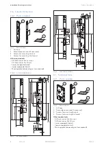
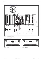
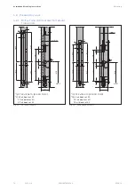
4.3.1  Mill-cut and drill door leaf for tubular 

frame locks

Fig. 19 

25

22

R6

131,5

20

4

,5

214

,5

14

1,5

*1)

OKFF

1050

*1)

ø10

10

10

*2)

2

5

1,

32/37 42

/

15

90

131

7

,5

*1) ST 3.9x19 A2-70 (EN ISO 7050)
*2) 45 at backset 35
      50 at backset 40
      55 at backset 45

SVI 2000/2000F

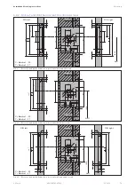
Fig. 20 

25

2

5

1,

22

R6

131,5

133,5

14

4

,5

14

1,5

*1)

ø10

15

90

131

7

,5

10

10

*2)

*1)

32/37 42

/

OKFF

1050

*1) ST 3.9x19 A2-70 (EN ISO 7050)
*2) 45 at backset 35
      50 at backset 40
      55 at backset 45

SVI 4000/SVI 5000

12

SVI Lock

2019-12

dormakaba Mounting instructions

Mounting

WN 059741 45532

Summary of Contents for SVI 2000

Page 1: ...ng plate 10 3 8 2 Rod striking plate 10 3 8 3 Switch lock 10 3 8 4 Lower rod guide 10 4 Mounting 11 4 1 Safety during mounting 11 4 2 Requirements for mounting 11 4 3 Preparatory work 12 4 3 1 Mill cut and drill door leaf for tubular frame locks 12 4 3 2 Mill cut and drill the door leaf for solid door locks 13 4 3 3 Prepare the floor for the masking plate 14 4 3 4 Prepare the door frame for the ro...

Page 2: ... door units SVA Active self locking anti panic lock for the active leaf in 2 leaf door units 2000 2000F 4000 5000 All versions of a lock the exact lock type is marked with 3 digits instead of zeros RR Tubular frame locks VB Solid door locks G Active leaf S Fixed leaf 1 5 Symbols used 1 5 1 Hazard categories WARNING This signal word indicates a possible hazardous situation which may result in death...

Page 3: ...these doors provide for the mounting and if the requirements in the usability certificates are followed The following SVI locks are suitable for use on fire and smoke protection doors SVI 5000 SVI 4000 SVI 2000F The SVI 2000 may only be used in fire and smoke protection doors in combination with the external Power Reserve module SVP PR DCW item no 70922601 2 2 Not intended use The lock may not be ...

Page 4: ...atus of the espagnolette bolt and the door handle panic bar 3 1 Installation situation 3 1 1 Mechanical opening Fig 2 1 2 7 3 5 6 8 9 S G 4 Mechanical installation situation example 1 Active leaf with SVA 5000 SVA 4000 or 6000 2 Fixed leaf with SVI 5000 SVI 4000 3 Panic door fitting 4 Cable transfer CT cable spiral CS and if necessary detachable cable transfer DT 5 Connecting cable SVP A 1100 2100...

Page 5: ...us applications The SVI 5000 is a mechanical lock When the door is closed the lock locks automatically The SVI 4000 is an electrically monitored lock When the door is closed the lock locks automatically The SVI 2000 is a motorized lock whose function can be controlled electronically When the door is closed the lock locks automatically It is operated separately Stand Alone or on an external control...

Page 6: ...ocks Fig 4 S G optional SVI SVA Fixed leaf with tubular frame lock 3 4 2 Solid door locks Fig 5 S G optional SVA SVI Fixed leaf with solid door lock 6 SVI Lock 2019 12 dormakaba Mounting instructions Product description WN 059741 45532 ...

Page 7: ... C DOP_0167 only with external PR module SVP PR DCW item no 70922601 3 5 2 Solid door locks dormakaba Deutschland GmbH DORMA Platz 1 58256 Ennepetal 0432 CPR 00026 11 18 SVI 2000 VB EN 179 2008 3 7 7 B 1 4 5 2 A C SVI 2000F VB SVI 4000 VB SVI 5000 VB 3 7 7 B 1 4 5 2 A C DOP_0162 0432 CPR 00026 02 18 SVI 2000 VB EN 1125 2008 3 7 7 B 1 4 2 1 2 A B C SVI 2000F VB SVI 4000 VB SVI 5000 VB 3 7 7 B 1 4 2...

Page 8: ...14 5 30 40 41 13 32 7 9 35 15 40 45 2 28 8 ø7 ø10 90 12 SVI 2000 2000F Fig 8 23 94 20 3 286 OKFF 1050 9 2 28 8 ø7 ø10 90 12 21 5 35 15 40 45 126 4 251 292 5 62 5 1 0 5 1 156 5 3 0 1 24 124 5 12 5 14 5 30 40 41 13 8 2 8 2 SVI 4000 SVI 5000 3 7 Solid door locks 3 7 1 Parts included Fig 9 1 3 4 2 Parts included 1 SVI Lock 2 Forend pre mounted if necessary 3 Screws for mounting the lock 4 Screws for m...

Page 9: ... OKFF 1050 X Y 20 R10 235 12 Position of the espagnolette bolt variable 4 4 2 on page 16 X Backset 35 Y Backset 27 C D C D A B Lock and forend dimensions forend depending on item ordered 3 7 3 Door versions Fig 11 SVA SVI SVI SVA A B Folding doors Fig 12 SVI SVA SVI SVA C D Rebated doors 9 SVI Lock 2019 12 dormakaba Mounting instructions Product description WN 059741 45532 ...

Page 10: ...onal 3 8 2 Rod striking plate Fig 15 ø10 5x90 ø5 5 64 5 80 20 24 60 22 8 75 12 3 40 Rod striking plate dimensions 3 8 3 Switch lock Fig 16 ø10 5x90 ø5 5 54 42 20 24 3 40 ø18 5 Switch lock dimensions 3 8 4 Lower rod guide Fig 17 ø10 4 60 20 40 20 ø15 13 3 ø11 6x90 ø6 Lower rod guide dimensions 10 SVI Lock 2019 12 dormakaba Mounting instructions Product description WN 059741 45532 ...

Page 11: ...ng is shown on a DIN left door For a DIN right door the procedure must be mirror inverted The mounting is shown with a long plate For other door fittings other mounting points may have to be used 4 2 Requirements for mounting The door corresponds to the specifications in Fig 18 and is deformed by a maximum of 5 mm For mounting along escape routes The door opens in the escape direction If the door ...

Page 12: ... 5 1 ST 3 9x19 A2 70 EN ISO 7050 2 45 at backset 35 50 at backset 40 55 at backset 45 SVI 2000 2000F Fig 20 25 2 5 1 22 R6 131 5 133 5 144 5 141 5 1 ø10 15 90 131 7 5 10 10 2 1 32 37 42 OKFF 1050 1 ST 3 9x19 A2 70 EN ISO 7050 2 45 at backset 35 50 at backset 40 55 at backset 45 SVI 4000 SVI 5000 12 SVI Lock 2019 12 dormakaba Mounting instructions Mounting WN 059741 45532 ...

Page 13: ... 38 ø7 ø7 ø22 OKFF 1050 85 1 24 13 0 18 13 235 209 55 19 6 8 2 5 38 6 8 6 8 65 80 100 2 5 6 8 78 min ø15 min ø15 X Y X Backset 35 Y Backset 27 Recesses and pre drilled holes in door leaf with a flat forend Fig 23 185 73 38 ø7 ø7 ø22 OKFF 1050 1 13 0 13 235 209 13 3 R10 3 55 19 6 8 2 5 38 6 8 6 8 65 80 100 2 5 6 8 1 13 0 13 235 209 13 3 R10 78 min ø15 min ø15 DIN right DIN left X Y X Backset 35 Y B...

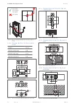
Page 14: ...ng plate Fig 26 2 60 33 ø 26 Recess for an adjustable masking plate optional 4 3 4 Prepare the door frame for the rod striking plate Fig 27 80 21 25 61 13 3 41 20 Recesses for the rod striking plate 4 3 5 Prepare the door leaf for the switch lock Fig 28 55 42 21 25 3 42 ø20 90 Recesses for the switch lock 4 3 6 Prepare the door leaf for the lower rod guide Fig 29 61 21 40 20 ø16 14 3 Recesses for ...

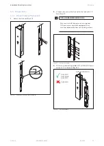
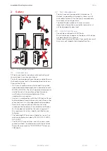
Page 15: ...COMMENDATIONS Only use the self locking screws supplied If these screws are loosened again they must be replaced by new self locking screws Fig 31 Screw on forend 3 Pull in the connecting cable SVP A 1100 2100 and connect it to the lock Fig 32 Fig 32 SVI 2000 SVI 2000F SVI 4000 SVI 5000 SVP A 1100 2100 100 Connect cable 15 SVI Lock 2019 12 dormakaba Mounting instructions Mounting WN 059741 45532 ...
Page 16: ... 45 X Dimensions of the adjustments 2 If necessary screw the forend to the lock Fig 36 with 1 5 Nm according to the DIN direction of the door TIPS AND RECOMMENDATIONS Only use the self locking screws supplied If these screws are loosened again they must be replaced by new self locking screws Fig 36 Screw on forend 16 SVI Lock 2019 12 dormakaba Mounting instructions Mounting WN 059741 45532 ...
Page 17: ...ty damage due to missing grub screw A missing grub screw at the top of the lock can cause the lock to be damaged Always screw the grub screw back into the lock 4 To change the screw in position of the espagnolette bolt if necessary Screw the grub screws at the top of the lock from one drill hole to the other HINWEIS If necessary the grub screws must be replaced by new self locking screws 5 Pull in...

Page 18: ...ble Fig 41 Door height in m Number of spacers 2 2 55 0 2 55 2 85 1 2 85 3 15 2 3 15 3 50 3 Special size Fig 41 1 2 Mount spacers 2 Determine and mark the length of the upper espagnolette bolt Fig 42 Fig 42 X Determine the length of the upper espagnolette bolt 3 Determine and mark the length of the lower espagnolette bolt Fig 43 Fig 43 X Determine the length of the lower espagnolette bolt 4 Shorten...

Page 19: ...to the lock by hand Fig 47 so that the espagnolette bolt can still be adjusted later Fig 47 Screw in upper espagnolette bolt 9 Insert the lower espagnolette bolt into the fixed leaf and screw it into the lock with 3 5 Nm Fig 48 Fig 48 3 5 Nm Screw in lower espagnolette bolt 10 Remove the locking clamp from step 6 from the SVI lock 11 Mount the switch lock at the top of the fixed leaf so that the i...

Page 20: ...nal Mount masking plate 16 Adjust the rod striking plate Fig 52 Fig 52 X X X 45 Dimensions of the adjustments 17 Mount the rod striking plate for the upper espagnolette bolt in the door frame Fig 53 Fig 53 M5 x 20 A2 70 Spax 4 5 x 30 Mount rod striking plate 4 5 2 Adjust upper espagnolette bolt 1 Disassemble the switch lock again 2 Operate the lock or push the upper espagnolette bolt fully into th...

Page 21: ...olette bolt 8 Mount the switch lock at the top of the fixed leaf again so that the inclined surface faces the door frame Fig 49 4 6 Fix upper espagnolette bolt 4 6 1 Tubular frame lock 1 Operate the lock so that the espagnolette bolts are retracted 2 Fix the upper espagnolette bolt through the drill hole in the forend with 1 Nm Fig 56 Fig 56 Fix espagnolette bolt 4 6 2 Solid door lock 1 Close the ...

Page 22: ...olor Duration Ready for operation 2000 ms 6 SVA 2000F integrated Power Reserve module test The internal Power Reserve module is tested 5 minutes after the power is turned on and then every 48 hours If the test completes with an error the corresponding flashing code appears once according to the error messages see chapter 9 The test is then performed a second time after a further 5 minutes If this ...

Page 23: ...e 6 This manual must be handed over to the facility operator and regular maintenance and recording duties must be observed see chapter 8 9 Error messages LED display Cause Action Power supply outside the tolerance range 24 V DC 15 Check power supply unit Power Reserve function test is faulty SVA 2000F only Call dormakaba Service Unlocking locking not successful Check whether the bolt is blocked fr...

Page 24: ...ock The actuating forces may be max 70 N for escape doors according to EN 179 and max 80 N for escape doors according to EN 1125 The actuating forces must not have changed significantly compared to the measurement after the initial installation 5 Clean the masking plate 6 Note the date of maintenance the corrective actions taken and the name of the person performing the work TIPS AND RECOMMENDATIO...

Reviews: