851-738 Rev. A
15
Dorner Mfg. Corp.
Brushless DC Motor Control
Operation
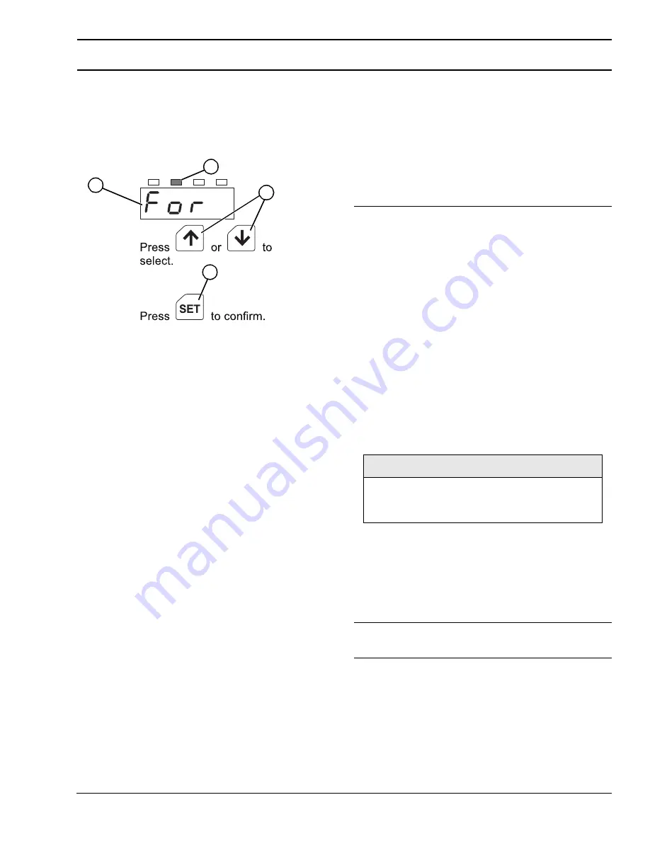
Set Motor Direction
The initial setting is “For” (clockwise).
1.
Press MODE to switch to the direction setting mode.
The F/R LED
will illuminate.
Figure 33
Figure 33
2.
Press up or down
to select a desired
direction. “For”
: Clockwise or
“rEv”: Counterclockwise.
3.
Press SET
to confirm the selection.
The display will blink.
Displaying the Conveyor Belt Speed
While the motor is operating, the speed of the motor output
shaft is displayed on the digital operator. To show the speed
of the conveyor belt (speed ft/minute), set the gear ratio to
the conveyor gear ratio in use.
1.
Calculate the conveyor gear ratio using the formula
below:
• Conveyor gear ratio =
• where:
• Gearhead ratio = ratio of inline or 90 degree gearbox
• Pulley diameter = Diameter of Drive Pulley (Ft)
- 2200 Series = 0.104
- 3200 Series = 0.25
- 2200 Precision Move End Drive Series = 0.125
- 2200 Precision Move Mid Drive Series = 0.167
- 3200 Precision Move End Drive Series = 0.275
- 2200 Modular Belt Series = 0.125
- 5300 Modular Belt Series = 0.325
- 5200 Modular Belt Series = 0.325
• Drive Sprocket Teeth = Number of teeth on sprocket
connected to gearmotor. Note: For all side drives = 1.
• Driven Sprocket Teeth = Number of teeth on sprocket
connected to conveyor shaft. Note: For all side drives = 1.
• Example:
- 2200 Series Conveyor with a 62M015PLBDDEN Gear-
motor and a light load bottom mount with a 44 tooth
pulley on the gearmotor and a 22 tooth pulley on the
conveyor.
• Conveyor gear ratio =
• Conveyor gear ratio = 21.5
F/R
4
1
3
2
(Gearhead Ratio) x (Drive Sprocket Teeth)
(4.28 Factor) x (Pulley Dia.) x (3.14) x (Driven Sprocket Teeth)
NOTE
To convert the display to meters/min., enter all
pulley diameters in meters and omit the 4.28
division factor in the equation.
(Gearhead Ratio) x (Drive Sprocket Teeth)
(4.28 Factor) x (Pulley Dia.) x (3.14) x (Driven Sprocket Teeth)
(15) x (44)
(4.28) x (0.104) x (3.14) x (22)


