background image


                                                                                               LEADING IN PRODUCTION EFFICIENCY 

Operating Manual 

© Dürr Systems AG 

ED3K_Operating_Manual_Rev02LD_03Lug2020_EN. docx 

Rev.02 – 03.07.2020 


OPERATING MANUAL 


Eco

Dose


3K


MDR00005EN 
Material number:   N10110001V 


Release :  

02 

Date :  

03.07.2020 


Eco

Dose


3K


Operating Manual 


Summary of Contents for EcoDose 3K

Page 1: ...ICIENCY Operating Manual D rr Systems AG ED3K_Operating_Manual_Rev02LD_03Lug2020_EN docx Rev 02 03 07 2020 OPERATING MANUAL EcoDose 3K MDR00005EN Material number N10110001V Release 02 Date 03 07 2020...

Page 2: ...ated this document in its last version applicable Version Changes Version of this document 02 dated 03 07 2020 Story of version changes Version Date Revision description 00 26 02 2019 Emission 01 03 0...

Page 3: ...or this Manual 17 3 2 Use of Tools in Ex Zones 18 3 3 Troubleshooting Instructions 18 3 3 1 Special Safety Notes 19 4 Transport and Storage 20 4 1 Transport 20 4 2 Storage 21 5 Description and operati...

Page 4: ...ualization window 50 8 5 1 System page functions 50 8 5 2 Cycle programs recipe selection 64 8 5 3 Spray valves 68 8 5 4 Spray data 71 8 5 5 Recipes data 72 8 5 6 Pre purge purge program 73 8 5 7 Cons...

Page 5: ...rr Systems AG ED3K_Operating_Manual_Rev02LD_03Lug2020_EN docx Rev 02 03 07 2020 8 12 3 Pot life lamp 114 9 Maintenance 115 9 1 Control panel 116 9 2 Fluidic panel 117 10 Parts List 120 10 1 Drawings...

Page 6: ...ct to amendment at the sole discretion of D rr Systems AG In case of amendments to the manual for further similar machines D rr Systems AG does not undertake to update the manuals for equipment alread...

Page 7: ...limb D A N G E R Danger of lethal injuries The red safety note Danger indicates a high risk that will result in death or a severe injury W A R N I N G Danger of severe injuries The orange safety note...

Page 8: ...angers The main rules for the prevention of accidents must be respected as well as the rules for safety The commands of EcoDose 3K have been designed exclusively for the activity of dosing components...

Page 9: ...rage temperature da 10 C a 40 C Power supply 100 240 Vac Frequency 50 60 Hz Breaking capacity 14kA Rated Power 130W Power consumption Coriolis 92W Power consumption Gear 60W Current consumption Coriol...

Page 10: ...1 to 30 1 25 350 25 350 2 1 1 40cc 2200cc 1 1 to 30 1 25 500 25 350 2 2 2 130cc 3200cc 1 1 to 30 1 25 500 25 500 For Mixing Ratio range 5 1 to 10 1 volume flow range will be 60cc 1200cc For Mixing Ra...

Page 11: ...er A B or C type 1 Volume Flow Range Mixing ratio Range Range Viscosity A CPS Range Viscosity B C CPS 40cc 3400cc 1 1 to 30 1 20 500 20 500 Color change block valves Low or high Pressure n color with...

Page 12: ...the Ex Zones Option Stand Alone 1 Flow control 7 Air manifold 2 Color change valves 8 Air filter 3 Filter product 9 Static Mixer 4 Pumping unit 10 Spray gun 5 Manual valve 11 EcoGun Cleaner M 6 Air r...

Page 13: ...tion Separated 1 Flow control 7 Air manifold 2 Color change valves 8 Air filter 3 Filter product 9 Static Mixer 4 Pumping unit 10 Spray gun 5 Manual valve 11 EcoGun Cleaner M 6 Air regulator 12 Remote...

Page 14: ...N Besides the observance of safety instructions therein described as far as transport operations installation normal functioning and maintenance are concerned also refer to the instructions contained...

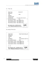
Page 15: ...15 LEADING IN PRODUCTION EFFICIENCY Operating Manual D rr Systems AG ED3K_Operating_Manual_Rev02LD_03Lug2020_EN docx Rev 02 03 07 2020 2 6 Plate data Atex marking of Fluidic Panel...

Page 16: ...ical electronic and programmable electronic control systems IEC 61439 General rule on electrical cabinets UNI EN ISO 13849 1 2016 Safety of machinery Parts of the safety related control systems Part 1...

Page 17: ...of the types of protection and the designation of protective devices broad knowledge of inspection maintenance and repair requirements in potentially explosive areas according to IEC 60079 17 If a pr...

Page 18: ...nt them and to prepare an operating manual on the basis of the resulting evaluation The customer has to ensure that all operators carrying out their own respective tasks know and observe these measure...

Page 19: ...irs you must make sure that EcoDose 3K does not contain any residual pressure air and product W A R N I N G Danger due to spraying or splashing material Potential chemical burns of the skin due to mat...

Page 20: ...The following operations can be performed only by adequately trained personnel See chap 3 of this manual C A U T I O N You must wear personal protective equipment Always wear the following equipment d...

Page 21: ...ev 02 03 07 2020 To remove EcoDose 3K from the wooden crate use the appropriate plank on the support frame C A U T I O N Use a lift strap with a payload of at least 500 kg 4 2 Storage The EcoDose 3K m...

Page 22: ...very circuits The circuits in which fluid components pass through are cyclically flushed with specific solvents The flushing cycles are controlled by pneumatic valves controlled by EcoDose 3K placed i...

Page 23: ...equipped with magnetic switches placed outside the glass of the booth which allows the operator staying in the cabin start the main controls with a magnet 1 Cabinet 2 Hinge 3 Operator panel 4 Magneti...

Page 24: ...s consist of a pressure generator 4 generally being a pump for the catalyst basic components and the flushing products A T T E N T I O N It is absolutely necessary for the products to be filtered thro...

Page 25: ...d to EcoDose 3K the equipment is activated and controlled with an air flowmeter that is installed in the control panel A filter 8 controls and protects EcoDose3K from dirt particles coming from the co...

Page 26: ...nents see the drawing Universal electrical cabinet Parts list Available to be attached to this Manual Pneumatic panel 1 Atomization air valves image indicative 2 Flow switch 3 Pressure switch 4 Series...

Page 27: ...nly by adequately trained personnel See chap 3 of this manual C A U T I O N You must wear personal protective equipment Always wear the following equipment during assembly operations 6 1 Electrical co...

Page 28: ...ICLES Class Max particles 1 Max concentration 2 1 0 1 micron 0 1 mg m 2 1 micron 1 mg m 3 5 micron 5 mg m 4 15 micron 8 mg m 5 40 micron 10 mg m 1 The diameter of the particle is based on the relation...

Page 29: ...Pneumatic connection Compressed air general power supply min 5 bar max 8 bar You must use the 1 2 gas F threaded connections You must use a flexible pipe of at least 1 2 gas Connection of the atomiza...

Page 30: ...e7 20 color low pressure change valves max 20 bar only used on circuit B hardener You must use threaded 1 8 gas female connection 1 2 EcoMCC200 high pressure color change valves max 160 bar with Corio...

Page 31: ...with Coriolis max 200 bar with Gear Used on circuit A base and on circuit B hardener W A R N I N G For the correct operation of the valves you must make sure that the tube RIF 1 is always full of comp...

Page 32: ...thout Low Pressure Regulator Flow One Spray Gun option complete with Low pressure regulator flow Double Spray Gun option complete with Low pressure regulator flow Use 1 4 gas 60 cone threaded connecti...

Page 33: ...O N For the correct functioning the supply pressure of the catalyst circuit must be higher 0 5 1 bar than the supply pressure of the base circuit This value may change depending on the viscosity of th...

Page 34: ...e color change valves EcoMCC 200 high pressure color change valves Coriolis Flow Control Gear Flow Control The number of cycles life of such components must be set the during installation depending on...

Page 35: ...skin due to material spurting from defective paint pipes and color changers You must regularly check paint pipes and color changer and you must reduce residual pressure before working on color valves...

Page 36: ...e automatically switched on Process values cycle quantities and sequences are deduced from a table recipe table purge program tables or from set and assigned parameters to individual components In thi...

Page 37: ...emi automatic External recipe mode automatic external The pictograms depending on the system status have different meanings Grey plant is shutdown Green plant is switched on and ready for use Red plan...

Page 38: ...v 02 03 07 2020 Left side menu The operating elements shown in the left side menu are used to navigate between the individual user interfaces Configuration window Spray window Recipe window Cycle prog...

Page 39: ...CTION EFFICIENCY Operating Manual D rr Systems AG ED3K_Operating_Manual_Rev02LD_03Lug2020_EN docx Rev 02 03 07 2020 8 4 Browsing windows 8 4 1 System page System page Figure 3 System page Spray page F...

Page 40: ...EADING IN PRODUCTION EFFICIENCY Operating Manual D rr Systems AG ED3K_Operating_Manual_Rev02LD_03Lug2020_EN docx Rev 02 03 07 2020 Spray data page Figure 5 Spray data page Recipe page Figure 6 Recipe...

Page 41: ...CTION EFFICIENCY Operating Manual D rr Systems AG ED3K_Operating_Manual_Rev02LD_03Lug2020_EN docx Rev 02 03 07 2020 8 4 2 Cycle program page Figure 7 Cycle program page 8 4 3 Parameters pages Figure 8...

Page 42: ...42 LEADING IN PRODUCTION EFFICIENCY Operating Manual D rr Systems AG ED3K_Operating_Manual_Rev02LD_03Lug2020_EN docx Rev 02 03 07 2020 Figure 9 Parameters page 2 Figure 10 Parameters page 3...

Page 43: ...43 LEADING IN PRODUCTION EFFICIENCY Operating Manual D rr Systems AG ED3K_Operating_Manual_Rev02LD_03Lug2020_EN docx Rev 02 03 07 2020 Figure 11 Parameters page 4 Figure 12 Parameters page 5...

Page 44: ...Operating Manual D rr Systems AG ED3K_Operating_Manual_Rev02LD_03Lug2020_EN docx Rev 02 03 07 2020 Valves operation number pages button located in parameters page 1 Figure 13 Valves operations page 1...

Page 45: ...NCY Operating Manual D rr Systems AG ED3K_Operating_Manual_Rev02LD_03Lug2020_EN docx Rev 02 03 07 2020 8 4 4 Pre purge and purge cycle page Figure 15 Pre purge and purge cycle page 8 4 5 Active alarm...

Page 46: ...perating Manual D rr Systems AG ED3K_Operating_Manual_Rev02LD_03Lug2020_EN docx Rev 02 03 07 2020 8 4 6 Alarm history page Figure 17 Alarm history page 8 4 7 Consumptions page button located in spray...

Page 47: ...ual D rr Systems AG ED3K_Operating_Manual_Rev02LD_03Lug2020_EN docx Rev 02 03 07 2020 8 4 8 External control interface signal page Figure 19 External interface control signal page 8 4 9 Calibration da...

Page 48: ...FFICIENCY Operating Manual D rr Systems AG ED3K_Operating_Manual_Rev02LD_03Lug2020_EN docx Rev 02 03 07 2020 8 4 10 User management page Figure 21 User management page 8 4 11 Reset passwords page Figu...

Page 49: ...49 LEADING IN PRODUCTION EFFICIENCY Operating Manual D rr Systems AG ED3K_Operating_Manual_Rev02LD_03Lug2020_EN docx Rev 02 03 07 2020 8 4 12 Settings page Figure 23 IP settings page...

Page 50: ...eration of each visualization window 8 5 1 System page functions Figure 24 switch mode System page 8 5 1 1 Switching the operating modes By tapping the mode symbol in the header a sub window opens thr...

Page 51: ...iency Tap on the button again to leave the manual mode and enter again the Recipe mode When the system is in recipe mode login with a level 1 or higher password tap on the button Ext Recipe mode on of...

Page 52: ...password entry menu choices language change start cycle programs save consumption data to USB stick change date and time 1 Expert worker duerr12 switch external recipe mode on off select active guns...

Page 53: ...ng_Manual_Rev02LD_03Lug2020_EN docx Rev 02 03 07 2020 Figure 26 Enter password page After confirming the password the currently active user level is displayed Figure 27 System page By tapping on the d...

Page 54: ..._Manual_Rev02LD_03Lug2020_EN docx Rev 02 03 07 2020 8 5 1 4 Date and time settings Date and time fields can be entered after tapping on each field In External recipe mode a specific command can be sen...

Page 55: ...secure the following data on a USB stick or to transfer them from a USB stick to the internal flash of the controller Recipe data Recipe table and Calibration data Calibration table Consumption data...

Page 56: ...07 2020 8 5 1 6 USB Data Save Load Operations 1 Insert USB stick in the IF4 USB port 2 Log in with appropriate user level 3 Select the action that you want to perform 4 Push this button to execute the...

Page 57: ...ons csv after saving Consumption to USB device E EcoDose3K_Weardata Wearcounters after saving the Wear counters to USB device With these files on the USB stick is possible to restore the complete conf...

Page 58: ...st user level Level 3 has the authorization to change passwords Figure 31 Page change password The level of the changed password Level 1 3 will be selected in the User level field After the new passwo...

Page 59: ...by pressing this key is used to reset user passwords The confirmation key to reset the passwords will appear if the correct PIN CODE is entered PIN CODE eco auc axb cyd Figure 33 Resetting all passwo...

Page 60: ...IP port connection the display is connected to the controller This address cannot be changed IP Address 192 168 102 100 Subnet Mask 255 255 255 0 Using the IF3 IP port connection the controller can be...

Page 61: ...required IP address can be entered using the corresponding input fields The input is activated through the confirmation button The menu can be left through the exit button In the display field IP IF3...

Page 62: ...below for all the channels A B and C Different calibration values are associated to each recipe Use the button to open the window in order to change the calibration values In this window the calibrati...

Page 63: ...y temporarily a row of the table Paste button using this button you can replace a previously row line with another Save button using this button you can save all the changes Tap on the row of the reci...

Page 64: ...rge calibration A calibration B and calibration C can be launched separately At the bottom left there are two pargraphs representing the progress of the various cycle programs for both the spray guns...

Page 65: ...programs defined in the recipe in use are launched in sequence on active guns Load to load the system The mixed quantities defined in the recipe in use are loaded in sequence on active guns Paint chec...

Page 66: ...e third section Test contains three displays Pulses for liter if this field is not already filled in go to the system page and press the button to open the calibration table Key in the theoretical val...

Page 67: ...to spray The atomization air is opened a gun is not in the EcoGun Cleaner M the EcoGun Cleaner M cover is closed and there are no alarms Undefined if the system is not in in any of the above listed s...

Page 68: ...n use YC number of the C channel valve of the recipe in use Mix ratio AB the mixing ratio of the recipe in use between A and B Mix ratio AC the mixing ratio of the recipe in use between A and C P Prog...

Page 69: ...annel B YC channel C valve BZL1 atomizing air pressure gun 1 BZL2 atomizing air pressure gun 2 YG 1 selection valve gun 1 YG 2 selection valve gun 2 BFDS color pressure valve BFDS1 mixed pressure gun...

Page 70: ...ve closes with touch The number of color and hardener valve to command is selected by means of dropdown menus near the valve symbol Interlocks do not allow to open more valves at the same time in the...

Page 71: ...he temperature and the density of fluids in A B and C channels are also available Current consumption during the spraying cycle in progress The consumption totalization can be activated locally pressi...

Page 72: ...ing ratio Color part for each B part MR A C Mixing ratio Color part for each C part POT Pot life of the mixed material LG1 LG2 Load quantity of spray gun 1 or 2 PG1 PG2 Purge program of spray gun 1 or...

Page 73: ...mporarily a row of the recipes table Paste button By using this button you can paste a previously copied line onto another Save button By using this button you can save all the changes made 8 5 6 Pre...

Page 74: ...OT total quantity of color and hardener solvent in milliliter EXA extra quantity of solvent channel A in milliliter EXB extra quantity of solvent channel B in milliliter EXC extra quantity of solvent...

Page 75: ...pes table Paste button By using this button you can paste a previously copied line to another Save button By using this button you can save all the changes made 8 5 7 Consumption Figure 43 Consumption...

Page 76: ...The file is saved daily in the folder F consumption with a name consisting of a pair of letters assigned in the parameters settings section 4 followed by the date of the day in which the file is writt...

Page 77: ...easured from channel A or B an alarm is raised after the seconds here specified Default value 2 s DELAY ALARM MIX RATIO ms When the mix ratio error is consistently greater than 1 an alarm is raised af...

Page 78: ...alue 20 ml min MINIMUM FLOW C ml min While spraying loading or purging the flow of the medium is controlled When the measured flow in channel C is consistently less than the quantity here specified an...

Page 79: ...LAY ALARM NO FLOW an acoustic alarm is raised The operator has still the time here specified to solve the problem and let the medium flow before the alarm stops the system Then a reset command on the...

Page 80: ...When the number operations of one of the valves connected to channel B is beyond this limit a warning message is generated If this limit is set to zero no warning messages are generated Provide for ma...

Page 81: ...here indicated the daily quantity consumed of solvents colors and components B and C for each recipe is saved in a CSV format file on the flash memory of the controller accessible by FTP connection Th...

Page 82: ...sistently out of the intervals here specified after the time specified in DELAY ALARM TEMPERATURE an alarm is raised If the temperature threshold values are set to 0 C this alarm is excluded DENSITY A...

Page 83: ...P 1 press the key to access the valves and flowmeter wear counters Figure 49 Valves operations page 1 Figure 50 Valves operations page 2 In order to reset the counters you must log in with user level...

Page 84: ...ctive alarms and alarms history Press the button at the page footer to toggle the windows view Actual alarms Alarm history 8 5 9 1 Actual alarms In this page are displayed all currently pending alarms...

Page 85: ...03Lug2020_EN docx Rev 02 03 07 2020 8 5 9 2 Alarm history Figure 52 Alarm history page Column 1 number of alarm group Column 2 number of alarm within the alarm group Column 3 alarm text Column 4 date...

Page 86: ...ow 8 POT life alarm 9 Calibration factor A or B or C less or equal to zero 10 POT life pre alarm 11 Plant switched off and not purged 12 External alarm 13 24V Power supply off 14 Mix ratio MR 1 out of...

Page 87: ...for channel B C Leakage on valve channel A Possible cause the flow meter of the paint base indicates that the product flows although the valve of the corresponding product is closed Fault elimination...

Page 88: ...et for the alarm see parameter DELAY ALARM NO FLOW PURGE LOAD Gun 2 not in gun flushing box same as above described but for gun 2 Analog input temperature A only with Coriolis flowmeter Possible cause...

Page 89: ...parameters TEMPERATURE ALARM THRESHOLDS Fault elimination check the fluid condition and the electrical connections Actual recipe zero Initialized to one Possible cause at the power up the actual recip...

Page 90: ...ents status and their connections Group 4 General system alarms Alarm number Alarm 0 Error in program initialization routine 1 Error in recipes initialization routine 2 Error in configuration initiali...

Page 91: ...guration save routine Error in parameters save routine Error in consumptions save routine External emergency Possible cause the safety relay is off due to an external cut off signal Fault elimination...

Page 92: ...connection Error in output regulation table Possible cause while working with closed loop flow control in automatic mode the output cannot be calculated for the request flow from the recipe regulatio...

Page 93: ...14 YVC1 valve has been activated too many times provide for maintenance 15 YVC2 valve has been activated too many times provide for maintenance 16 YVC3 valve has been activated too many times provide...

Page 94: ...data in required recipe 37 Wrong purge program in required recipe 38 YRF1 valve has been activated too many times provide for maintenance 39 YRF2 valve has been activated too many times provide for m...

Page 95: ...an open the external recipe mode window by touching this button Figure 53 External interface control signal page This page summarizes input and output signals that are received from the external plc w...

Page 96: ...mode 20 2 mStatFault BOOL Global Fault Station 20 3 mStatWarning BOOL Global Warning Station 20 4 mAckSetTime BOOL Acknowledge date and time sync request 20 5 mSpare_20_5 BOOL 20 6 mSpare_20_6 BOOL 2...

Page 97: ...eSate2_11 BOOL YV1C Valve On 46 4 iValveSate2_12 BOOL Valve 46 5 iValveSate2_13 BOOL Valve 46 6 iValveSate2_14 BOOL Valve 46 7 iValveSate2_15 BOOL Valve 47 0 iValveSate2_00 BOOL YG1 Valve On 47 1 iVal...

Page 98: ...63 5 mPotLifeAlarm BOOL System in pot life alarm 63 6 mPotLifePrealarm BOOL System in pot life pre alarm 63 7 mSpare_63_7 BOOL 64 0 mSpare_64_0 BOOL 64 1 mSpare_64_1 BOOL 64 2 mSpare_64_2 BOOL 64 3 m...

Page 99: ...OOL Set date and time from external control 20 3 mSpareO_20_3 BOOL 20 4 mSpareO_20_4 BOOL 20 5 mSpareO_20_5 BOOL 20 6 mSpareO_20_6 BOOL 20 7 mSpareO_20_7 BOOL 21 0 mSpareO_21_0 BOOL 21 1 mSpareO_21_1...

Page 100: ...eG2Active BOOL Main needle Gun 2 active 62 6 mTpAbort BOOL Abort Program 62 7 mStartCons BOOL Start consumption measure 63 0 mSpareO_63_0 BOOL 63 1 mSpareO_63_1 BOOL 63 2 mSpareO_63_2 BOOL 63 3 mSpare...

Page 101: ...tems AG ED3K_Operating_Manual_Rev02LD_03Lug2020_EN docx Rev 02 03 07 2020 8 9 External interface flowchart Example recipe selection from 1 to 100 Timing Diagram external control interface Example On o...

Page 102: ...ENCY Operating Manual D rr Systems AG ED3K_Operating_Manual_Rev02LD_03Lug2020_EN docx Rev 02 03 07 2020 Example consumption measure Example life signal of telegram counter Example abort active cycle p...

Page 103: ...the X20CP1381 B R module must be used On EcoDose control a UDP server is programmed the corresponding external control must be programmed to connect a UDP client On the external control the following...

Page 104: ...page SETUP 4 activate when available the flow control option Closed loop Figure 55 In this condition assigned a flow set point value while spraying the control pressure of the regulator is consistent...

Page 105: ...ue of the set point in ml min and on the right the system status the value of the regulator output in percentage and in bar the current measured value of the flow A green circle near the gun s trigger...

Page 106: ...s configured as closed loop operating the regulator in manual mode the system can be controlled while spraying as if it were regulated in pressure Press on the key to access the recipe regulation data...

Page 107: ...wait for the indicated flow to be stabilized write the values of the percentage output and the corresponding flow in the table The points describe a curve which should cover the range of the possible...

Page 108: ...ating the data the calculated output to the regulator is 31 8 at 20 5 C Spraying at 25 C 20 5 25 0 8 3 6 and the corrected output 31 8 3 6 28 2 The value of K has to be determined experimentally gener...

Page 109: ...key An automatic procedure is carried out where the sequence of the set points written in the recipe is assigned to the output and the corresponding values of the measured flow saved in the recipe re...

Page 110: ...Default value 200 s Minimum value 0 maximum 100000 Deadband The regulator output is frozen when the flow error is contained within the deadband Default value 3 ml min Output Maximum table deviation W...

Page 111: ...he regulator output gets quickly frozen If material is passing and still the gun trigger indicator the circle in the regulator page next to the trigger is red coloured reduce the value of this paramet...

Page 112: ...External interface signal Figure 67 flow regulation External interface control signal page In external recipe mode when the option closed loop is active flow can be controlled through the signal inte...

Page 113: ...white lamp is flashing Activate again the switch while the cycle is running to stop it Once the system is purged the white lamp is steady on LOAD to start a loading cycle The magnet must be placed in...

Page 114: ...a short time to increase or decrease the required recipe number Activate the confirmation sensor with the magnet The actual recipe number is then updated Loading operation can be started The panel sh...

Page 115: ...sembly operations W A R N I N G Before performing any maintenance on EcoDose 3K the operator must ensure that the power is shut down air and product supplies are intercepted all circuits product solve...

Page 116: ...rol panel The electrical equipment must be examined once a year to ensure it is in a suitable condition In particular check the correct tightening of terminal screws image indicative The EcoDose 3K PL...

Page 117: ...ed periodically following the manufacturer s instructions attached to this manual The valve activity is controlled by the PLC and if the number of switching operations carried out exceeds the programm...

Page 118: ...ans of calibration After about 8000 hours of activity the calibration must be controlled by the manufacturer The activity of the gear flowmeter is controlled by the PLC and if the number of switching...

Page 119: ...If there should be the need of removing one or both GEAR FILTER from the mixing panel due to the particular kind of paint and or catalyst used proceed as follows A Remove the GEAR FILTER B Loosen the...

Page 120: ...040 CM GE 04 00 EcoDose 3K general assembly CORIOLIS flowmeter version HP 0300040 DT GE 01 00 Universal fluidic panel_CORIOLIS flowmeter_HP 0300040 DT GE 02 00 Universal fluidic panel_GEAR flowmeter_H...

Page 121: ...012 Valves CC EcoMCC 200 2C D SST N14100001 Valves CC EcoMCC 200 4C D SST N14100002 Valves CC EcoMCC 200 8C D SST N14100004 Valves CC EcoMCC 200 10C D SST N14100005 Valves CC EcoMCC3 20 2C N14800102 V...

Reviews: