80
LEADING IN PRODUCTION EFFICIENCY
Operating Manual
© Dürr Systems AG
ED3K_Operating_Manual_Rev02LD_03Lug2020_EN. docx
Rev.02 – 03.07.2020
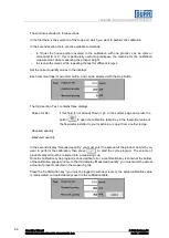
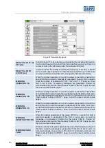
Figure 47 Parameters page 4
DELAY VALVE YF (A)
OFF [ms]
In order to keep YF color valve always open during the component B injection,
it can be kept opened for a short time here specified, even when there is a
surplus of color in the A/B mixing ratio. Default value 300 [ms]
DELAY VALVE YB
(C) OFF [ms]
In order to reduce the number of operations (frequency) of the B ( C ) channel
valve, it can be kept opened for a short time here specified, even when there
is a surplus of B (C) in the A/B ( A/C ) mixing ratio. Default value 0 [ms]
WARNING
OPERATION VA
When the number operations of one of the valves connected to channel A is
beyond this limit, a warning message is generated. The same limit is used to
check the number of operations for YG1, YG2 and YT1, YT2 valves. If this
limit is set to zero, no warning messages are generated. Provide for
maintenance and press the “Rest counters” button in SETUP 1 page, to enter
the reset counters values pages..
WARNING
OPERATION VB
When the number operations of one of the valves connected to channel B is
beyond this limit, a warning message is generated. If this limit is set to zero,
no warning messages are generated. Provide for maintenance and press the
“Rest counters” button in SETUP 1 page, to enter the reset counters values
pages.
WARNING
OPERATION VC
When the number operations of one of the valves connected to channel C is
beyond this limit, a warning message is generated. If this limit is set to zero,
no warning messages are generated. Provide for maintenance and press the
“Rest counters” button in SETUP 1 page, to enter the reset counters values
pages.
WARNING
OPRATION YRF-YHN
When the number operations of the valves YRF1/2 is beyond this limit, a
warning message is generated. If this limit is set to zero, no warning
messages are generated. Similarly for the valves YHN1/2. Provide for
maintenance and press the “Rest counters” button in SETUP 1 page, to enter
the reset counters values pages.
WARNING PULSE
FLOW
When the number of impulses generated by one of the flowmeters is beyond
this limit, a warning message is generated. If this limit is set to zero, no
warning messages are generated. Provide for maintenance and press the
“Rest counters” button in SETUP 1 page, to enter the reset counters values
pages.

