12 – Examples
VLM-40 NTSC T
ECHNICAL
I
NSTRUCTION
M
ANUAL
OPERATION
S
ETUP
L
EVEL
V
IOLATION
E
XCESSIVE
P
EAK
L
UMINANCE
COMPOSITE VIDEO LUMINANCE METER
MODEL VLM-40
-48
-40
0
20
40
60
80
100
120
© 1990
SYNC
LUMINANCE
IRE UNITS
-32
SYNC
SETUP
IRE Units
100
80
60
40
20
-20
-40
0
setup = 7.5
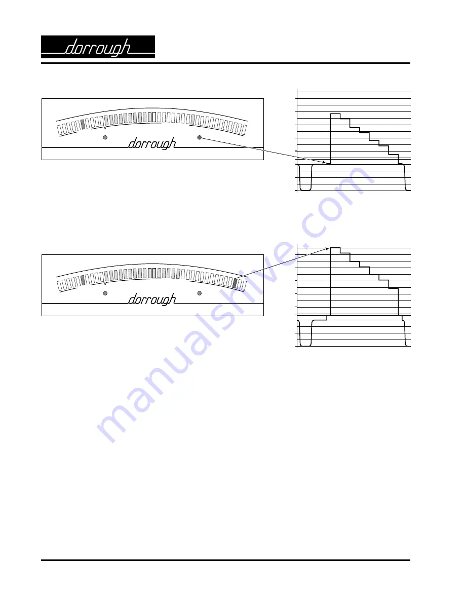
Fig. 14. On the VLM-40, the setup LED is red. On the waveform
monitor, the setup level is less than 4 IRE.
IRE Units
100
80
60
40
20
-20
-40
0
setup = 7.5
COMPOSITE VIDEO LUMINANCE METER
MODEL VLM-40
-48
-40
0
20
40
60
80
100
120
© 1990
SYNC
LUMINANCE
IRE UNITS
-32
SYNC
SETUP
Fig. 15. On the VLM-40, average luminance levels are at acceptable
levels, but the red peak LED indicates peak luminance levels are above
100 IRE. This condition frequently occurs in a scene when light is
reflected (e.g., jewelry) or there is external noise. Depending on the
duration of the peak signal, you may not easily see these waveform
excursions on a waveform monitor.


