8 – Reading The VLM-40
S
YNC
L
EVELS
...
VLM-40 NTSC T
ECHNICAL
I
NSTRUCTION
M
ANUAL
OPERATION
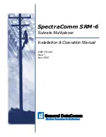
Sync level is displayed (left corner of VLM-40) as a single lit
green LED within a range of ten yellow LED segments from
-52 to -32 IRE. Each LED equals 2 IRE units. The indicated value
corresponds to the value of the sync tip on a waveform
monitor, as shown in Fig. 8.
NOTE: A sync LED provides a simple presence/absence indicator of
sync levels. The thresholds are:
Sync Level
Sync LED Color
-52 to -32 IRE
Green
-32 IRE or higher
Red
No Sync
Red
IRE Units
100
80
60
40
20
-20
-40
0
setup = 7.5
COMPOSITE VIDEO LUMINANCE METER
MODEL VLM-40
-48
-40
0
20
40
60
80
100
120
© 1990
SYNC
LUMINANCE
IRE UNITS
-32
SYNC
SETUP
COMPOSITE VIDEO LUMINANCE METER
MODEL VLM-40
-48
-40
0
20
40
60
80
100
120
© 1990
SYNC
LUMINANCE
IRE UNITS
-32
SYNC
SETUP
IRE Units
100
80
60
40
20
-20
-40
0
setup = 7.5
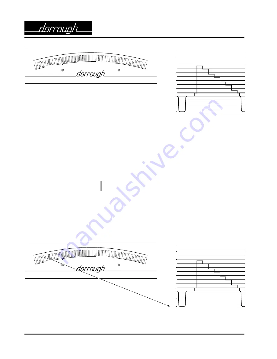
Fig. 7. VLM-40 and waveform monitor each show a 75% full-field
color bar signal at 115 IRE p-p with low-pass filter on. On the VLM-40,
three video levels are displayed: sync = - 40 IRE, average luminance =
40 IRE, and peak luminance = 76 IRE (75 actual). The total of the
sync and peak luminance excursions equals 115 IRE. The sync LED is
green and the setup LED is green.
Fig. 8. Sync level on the VLM-40 corresponds to sync tip on
the waveform monitor.


