Page
|
3
REV#0001A
THRU BOLT MOUNTING IN SOLID CORE WOOD DOOR
Drill 11/32” h ole throu gh th e door for t he s houlder bolt a nd the n e nlarge the opening on the outsi de of the d oor to 1/2” to
accommodate the sex nut (F igure 4). Insert shoulder screw/armature assembly through face of door, being sure th at spring
washers remain over shoulder, and hold firmly against door by pushing directly on head of screw. Insert sex nut from opposite
face and assemble. When armature is floating freely, tighten 5/16-18-shoulder screw fully and securely with 5-32 Allen wrench
.
STEP 4) LOCK & ARMATURE ALIGNMENT
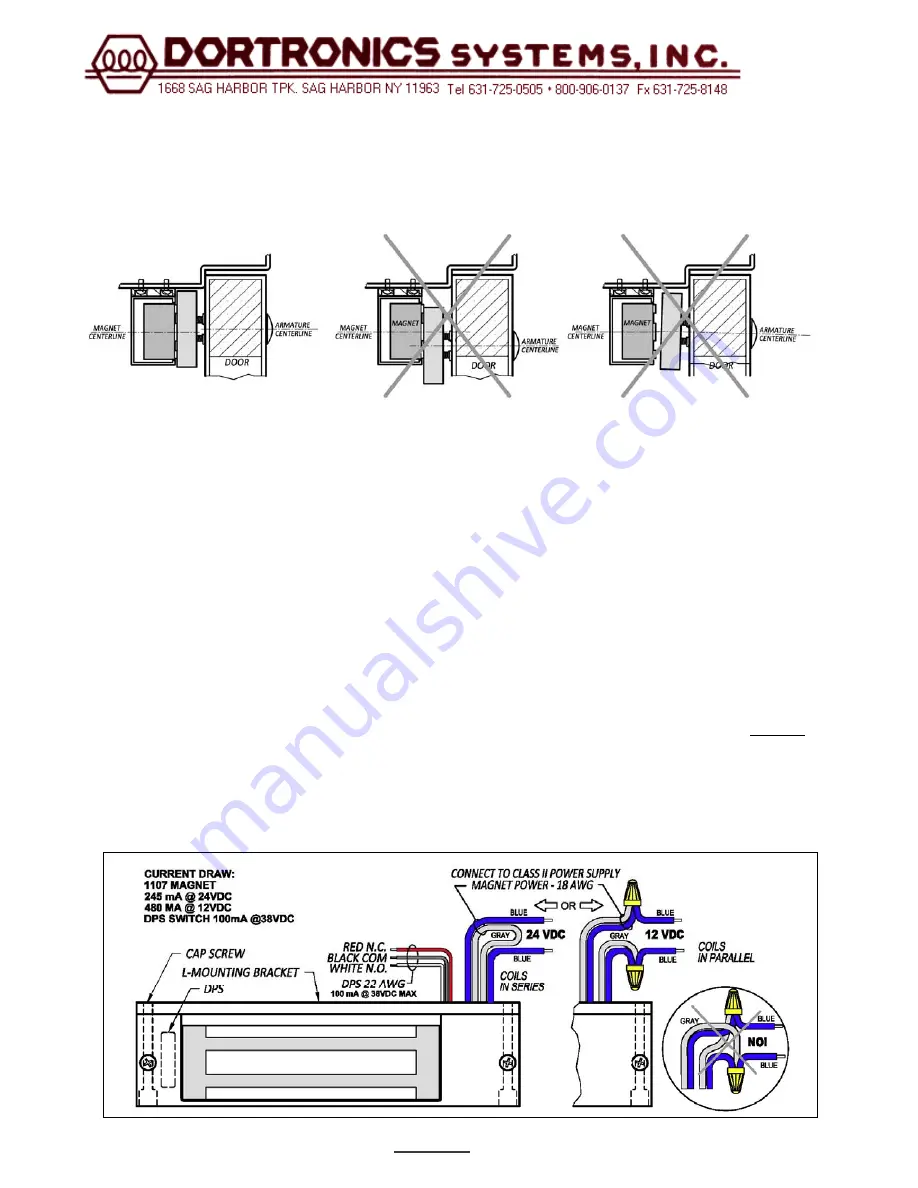
Make all electrical connections per figure 6 below. Attach the electro-magnet to the mounting plate using the (2) 1/4“cap
screws and split washers,
do not over tighten the cap screws they will need to be removed for final adjustment.
With the el ectro-magnet energized and the armature fully engaged, position the Lock so that t he door is snu g against stops
mark the p osition of the lock mounting plate; then
Turn the system off
. Remove the (2) 1/4“cap screws, remove the electro-
magnet and fully tighten the (4) screws that hold the lock mounting plate to the header.
Using the ( 2) 3/16” dia. holes in the m ounting plate as a physical template prepare the f rame for the (2) locking screws. Drill
.159 dia. Holes (No. 21 drill) and tap frame for No. 10-32 machine screws, or drill two 11/64” dia. in the frame for No. 10 sheet
metal screws. Secure mounting plate with #10 screws and lock washers.
The use of the # 10 locking screws is important.
They provide resistance to shear and rotation, and assure that maximum holding force is developed.
Re-install the electro-magnet using the 1/4” cap screws and check installation and alignment of armature and electro-magnet
by opening and clos ing door while turning system on and off. Armature mounting surface must be in full c ontact with top and
bottom rails of electro-magnet
ELECTRICAL HOOKUP
The 1107 electro-magnetic lock should be connected to a Class 2 power supply
. Leads are connected in series for 24
volt operation (as shipped from the factory) or connected in parallel for 12 volt operation.
For 12 volt operation
, cut the gray
wire to m ake 2 equal lengths, strip back the insulation 3/8” on each lead and connect each gray wire end to the c loser blue
wire end – see Figure 6 below.
Note: For 12 VDC (parallel coils) the gray wire must be connected to the adjacent blue
wire or the magnetic bond will be significantly reduced.
If the Door Position Switch option is installed, connect the black 22 AWG wire to the common connection of the access control
input for monitoring door status. Then connect either the red wire (for systems requiring normally closed contacts) or the white
wire (for s ystems requiring normally open contacts). Refer to t he device manual for det ails. Typically, Dortronics door control
systems look for closed contacts to indicate that the door is secure (closed).
Figure
6
Figure
5
Summary of Contents for 1107 D Series
Page 4: ...Page 4 REV 0001A Figure 7...
Page 6: ......


