4300 MANUAL
1.2
Page
3
of
6
rev. 12/9/2021
DORTRONICS SYSTEMS. INC
DOOR POSITION SWITCHES
Door switch contacts must be closed when the door is secure. Twisted pair wiring – AWG gauge 22 or larger
is recommended.
REQUEST FOR ACCESS DEVICES
Door unlock time is determined by an external device, typically a card reader, motion sensor, pushbutton or
remote console. Only normally open dry contacts should be used. Do not apply voltage to a 4300 input.
DOOR LOCKS
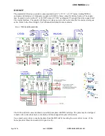
Maglocks and strikes are connected to the powered outputs directly. Both powered outputs are fused. LED
indicators to indicate lock status may be wired in parallel (as shown)
NOTE:
Connect Maglocks to the normally closed relay contacts and fail-secure electric strikes to the normally open
contacts so that the door is unlocked when the associated relay is energized. Fail-safe strikes (unlocked when
power is removed) should be connected to the normally closed contacts.
Use a wire of sufficient diameter and rating to minimize voltage drop, especially over long wire runs. AWG
18 gauge is recommended for power circuits. Do not connect loads greater than 1.5 Amps to a powered
output. Make sure diodes are used on maglocks to prevent back EMF (standard on most Dortronics locks).
TRAFFIC AND LOCK STATUS LIGHTS
LED and incandescent indicator lights (typically red to show a locked or inaccessible condition and green to
show an unlocked or freely accessible condition) may be connected as shown in Figure 2. Note that the red
LED can be connected in parallel with the maglock and the green in parallel with a strike, or they may be
connected to the dry contact non-fused outputs (RLY 1 = Door 1).
AWG 22 gauge or larger is recommended for signaling and low-power indicator circuits.
PANIC EGRESS OR REMOTE UNLOCK
The 4300 controller includes a remote lock override function. The Remote lock override terminals (Fig 1G)
may be connected to a set of dry contacts. On closure, the associated door lock relay will energize, unlocking
the door and bypassing the interlock function for as long as the switch contacts are closed.
Both doors can be unlocked simultaneously by using a double pole double throw switch. Multiple DPDT
switches can be used in parallel if needed, but be sure to wire them correctly. The Lock Override function is
separate and in addition to the fire alarm connection on the power supply. The override is useful to unlock
doors in the event of a door position switch failure, a stuck door, an environmental emergency or any other
reason that requires immediate egress regardless of interlock status.
Building codes vary by location. The installer is responsible for understanding and working in compliance
with all local codes and regulations as defined by the governing authority.
TESTING
Indicator LEDs for each relay indicate if the relay is energized. There are 2 output relays and 2 logic relays.
The action of the logic relays will depend on the desired type of operation, and is selectable by changing the
jumper configuration (Fig 1C). Make sure the pattern of jumpers is correct for the operation required. Doors
should be unlocked when relays are energized. Door position switch contacts should be closed when the door
is closed.
Caution: Do not short the powered outputs!
If a fuse blows, replace it with the proper value -
1.6 Amp
quick blow.


