Pag
3
di
4
Introduction
: The residual current devices, type A, AC Dossena DER3 series, fully compliant with IEC 60947-2: 2019, can be used in LV network in AC TT and TN type.
The series offers a wide range of adjustment of the I∆n threshold (up to 30 A) and of the delay time (up to 10 sec). DER3 guarantees ease of use, reliability, and speed
of programming. The measures and parameters are clearly displayed. The variation of the background colour immediately indicates the instrument’s operating status
(Green = residual current protection active, Blue = setup, Red = Alarm / Intervention).
INSTALLATION SUGGESTIONS AND SAFETY PRECAUTION:
All installation and maintenance operations must be carried out by qualified personnel in the absence of voltage and in a total electrical safety regime, in compliance
with the safety regulations.
1) Before powering the DER3, check that all connections have been executed properly.
2) ALWAYS install DER3 combined with Dossena toroidal transducer D series.
3) The cross-section of the conductors must be such that the total resistance of each DER3 ↔transducer connection is less than 0.5Ω.
4) Minimize the distance connections between DER3 and transducer and keep them away from power cables; use twisted shielded cables with the shield connected
to ground at one point only (keep the measurement circuit separate from test circuit).
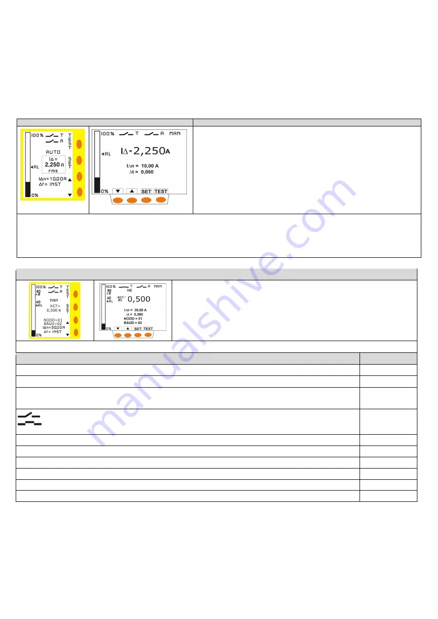
NORMAL VIGILANCE (GREEN DISPLAY)
(
I∆):
Display in true rms value (TRMS) of the residual current in A.
(I∆n):
Set threshold of the nominal residual current
∆t=
Set limiting non-actuating time
Histogram:
represents the measurement of the residual current of the system in% of I∆n
(only for DER3/2D - 2I - 2IM)
AL
= alarm threshold (only for DER3/2D - 2I - 2IM)
Keys functions:
▲
▼
= possibility to adjust the display contrast
SET
= press for at least 3 seconds to enter in SET UP
TEST
= press to perform DER3 test, push for at least 10 seconds to start DER3 special test
RESET
= Reset button for the manual reset.
TEST
: The test checks the complete protection system (DER3+ toroids series D + T.C.). Push test button to start the test. Display becomes red. TRIP relay and 2
nd
relay
change state. Danger signal and message “TRIP” appear flashing. Press “RESET” button to reset, if the reset mode is manual (MAN).
SPECIAL TEST:
The special test (only possible with T.C.) checks the complete protection system without T.C. tripping; it can be executed only if the TRIP mode is set
normally de-energized N.De. Press the test button for 10 seconds to perform the special test. At the end of test, if the display is green, the message "TEST OK" and
the danger signal are flashing, the test has been successful. No relays switch. Otherwise, the display flashes red and yellow and the message “REL.BA” flashes, the
test has failed and the 2
nd
relay switches.
Note
: In case of strong electromagnetic disturbances the display may go blank or irregular: push the button
▲
or
▼
to restore the normal display.
SETUP (BLU DISPLAY)
1 -
push SET button for at least 3 seconds to enter in SETUP(
display becomes blue)
2- push quickly SET button to select cyclically the parameter to modify (it will appear flashing)
3- push
▲▼
buttons
to modify the selected parameter
4-
push SET button for at least 3 seconds to exit from SETUP and save the parameters
(display
returns green).
DER3 automatically exits from SETUP without saving modification after 3 minutes of inactivity.
Note
: The new setup parameters will be operative only after saving. If an alarm occurs in setup, it is caused by the previously set parameters.
PARAMETERS
RANGE
[DEFAULT]
I∆n (A)=
Threshold of the nominal residual current: when IΔ exceeds I∆n TRIP relay switches.
0,03 ÷ 30A
[0,03A]
ΔT=
Limiting non-actuating time. If you set it to "INST", the tripping mode becomes instantaneous.
0,06 ÷ 10sec
[0.06
S
]
T –
The 2
nd
relay is second TRIP relay: it switches at the same time of TRIP relay (the trip coil must be
always
connected to TRIP relay).
A –
The 2
nd
relay is alarm relay. It switches when set alarm threshold is exceeded (only DER3/2D-2I-2IM).
T/ A
[A]
N.de. =
Trip relay is normally de-energized (N.De.) and it energizes when IΔ exceeds set I∆n
NE=
Trip relay is normally energized (N.E.) and it de-energizes when IΔ exceeds set I∆n. Setting TRIP as normally energized N.E.
(positive security) disables the permanent verification of T.C. and its power.
N.De. - N.E.*
[N.De.]
MAN/AUTO
: Reset mode: manual or automatic.
MAN- AUTO
[MAN]
◄
AL
: Threshold of Alarm (% of IΔn).
20% ÷ 80%
[50%]
<R
: Hysteresis: threshold in percentage value of IΔn.
30% ÷ 80%
[80%]
KCT
= transformation ratio of toroids. For "Series D" it is 0.500 K. Set to 5 only with the use of toroids D80S and D300M.
0,001 ÷ 30
[0,500]
NODE
= Configuration network node: assign to each DER3 a node number (only for versions equipped with serial output RS485)
1 ÷ 247
[1]
BAUD
= Serial baudrate configuration (only for versions equipped with serial output RS485)
4800 ÷ 38400
[19200]
* Warning:
the safety condition N.E, is applied exclusively to the TRIP relay and not to second relay even if it is set in TRIP condition.


