45
45
Helm Control Systems
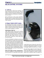
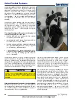
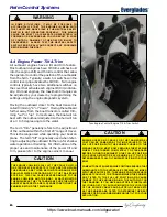
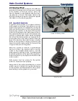
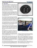
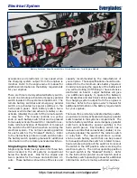
The engine controls and key pads have integrated
switches and indicator lights which allow the op-
erator to control all aspects of the boat’s propul-
sion system. LED lights on the control pad indicate
that the control is activated and the engines can
be started.
The most common features activated or
monitored by the keypad are:
• Starter lockout, which prevents the engine
from being started in gear.
• Gear lockout, which allows the engine RPM to
be advanced in neutral safely.
• Battery voltage warning indicator that warns
the operator of high or low voltage supplied
to the system (audible alarm)
• An engine synchronization feature that auto-
matically keeps both engines at the same RPM
while cruising. Refer to Engine Synchronizing
in this section and the control systems owner’s
manual for more information regarding engine
synchronization.
• Trolling feature that allows the operator to in-
crease the engine speed in 50 RPM increments
while operating at trolling speeds between
600 - 1000 RPM.
These features and others not mentioned require
specific procedures to activate and operate them
properly. Some of the procedures and features
are unique to the engines and other options
installed on your boat. It is essential that you
read the owner’s manual for the controls and be
completely familiar with their operation before
using your boat.
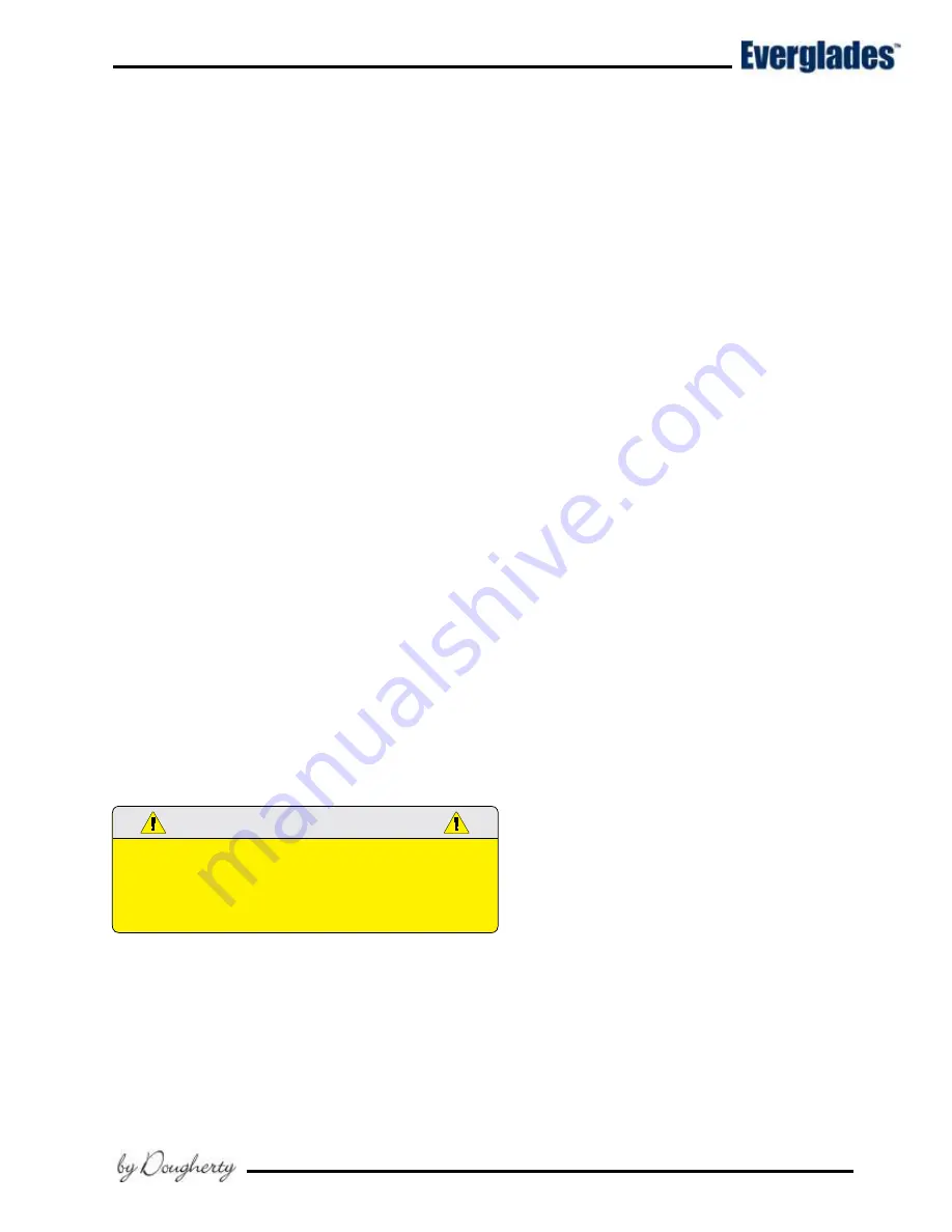
CAUTION
ALWAYS RETURN THE ENGINE THROTTLE LEVER TO THE
EXTREME LOW SPEED POSITION BEFORE SHIFTING.
NEVER SHIFT THE UNIT WHILE ENGINE SPEED IS ABOVE
IDLE RPM.
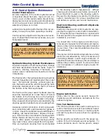
Engine Synchronizer
During most operations of a twin engine boat, it is
advantageous for both engines to be operated at
the same RPM. This reduces noise and vibration
and can increase engine efficiency. Setting the
throttles so that the engines are running the same
RPM (synchronized) can be done by listening to
the engine sounds at low RPM and with the auto-
matic synchronizer feature built into the electronic
engine controls when the engines are operating
above 1000 RPM. Attempting to synchronize the
engines solely by using the tachometer readings
or control lever placement generally will not work.
When the engines are in proper synchronization,
the throttle levers may not necessarily be even.
Refer to the engine or control owner’s manuals for
more information on the engine synchronizer and
other features for the electronic controls installed
on your boat.
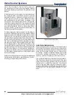
4.3 Neutral Safety Switch
Every control system has a neutral safety switch
incorporated into it. This device prohibits an en-
gine from being started while the shift lever is in
any position other than the neutral position. If
the engine will not start, slight movement of the
shift lever may be necessary to locate the neutral
position and disengage the safety cutout switch.
Control adjustments may be required to correct
this condition should it persist. See your dealer
for necessary control adjustments.
Neutral safety switches should be tested periodi-
cally to ensure that they are operating properly.
To test the neutral safety switches, make sure the
engines are tilted down and move the shift levers
to the forward position.
Make sure the throttle control levers are not
advanced past the idle position.
Press the
Start button or turn the key just long enough to
briefly engage the starter for the engine.
Notice:
Some outboard control systems are equipped
with a computer controlled start feature that
will keep the starter engaged until the engine
starts if the neutral safety switch fails and
allows the starter to engage.
The starter should not engage for any engine.
Repeat this test with the shift levers in reverse
and the engine throttles at idle. Again, the starter
should not engage for any engine. If the starter
for any engine engages with the shift controls in
any position other than the neutral position, then
the neutral safety switch is not functioning prop-
erly and you should contact your dealer to have
the neutral safety switch repaired by a qualified
marine mechanic before using the boat. If an
engine starts in gear during this test, immediately
move the control lever to the neutral position and
turn the engine off.
https://www.boat-manuals.com/edgewater/
Summary of Contents for Everglades 273CC
Page 1: ...EVERGLADES OWNER S MANUAL 273CC https www boat manuals com edgewater...
Page 2: ...2 Revision 0 03 29 2017 https www boat manuals com edgewater...
Page 14: ...14 NOTES https www boat manuals com edgewater...
Page 23: ...23 Operation https www boat manuals com edgewater...
Page 36: ...36 NOTES https www boat manuals com edgewater...
Page 58: ...58 NOTES https www boat manuals com edgewater...
Page 76: ...76 NOTES https www boat manuals com edgewater...
Page 80: ...80 NOTES https www boat manuals com edgewater...
Page 84: ...84 NOTES https www boat manuals com edgewater...
Page 108: ...108 NOTES https www boat manuals com edgewater...
Page 122: ...122 NOTES https www boat manuals com edgewater...
Page 123: ...123 SCHEMATICS Appendix A https www boat manuals com edgewater...
Page 124: ...124 NOTES https www boat manuals com edgewater...
Page 130: ...130 Maintenance Log Hours Date Dealer Service Repairs https www boat manuals com edgewater...
Page 131: ...131 Maintenance Log Hours Date Dealer Service Repairs https www boat manuals com edgewater...
Page 132: ...132 Maintenance Log Hours Date Dealer Service Repairs https www boat manuals com edgewater...
Page 133: ...133 Maintenance Log Hours Date Dealer Service Repairs https www boat manuals com edgewater...
Page 134: ...134 Maintenance Log Hours Date Dealer Service Repairs https www boat manuals com edgewater...
Page 135: ...135 Appendix D BOATING ACCIDENT REPORT https www boat manuals com edgewater...
Page 136: ...136 Boating Accident Report https www boat manuals com edgewater...
Page 137: ...137 Boating Accident Report https www boat manuals com edgewater...
Page 138: ...138 NOTES https www boat manuals com edgewater...
Page 140: ...140 NOTES https www boat manuals com edgewater...
Page 145: ...CAUSE AND SOLUTION https www boat manuals com edgewater...

