background image

Lit. No. 72936, Rev. 01 

16 

October 15, 2019

1.  Install the control side of the bracket to the vehicle 

side using 1/4" x 1/2" Phillips head machine 
screws, 1/4" nylon shoulder washers, 1/4" lock 
washers, and 1/4" locknuts.

2.  Plug the vehicle control harness into the cab control.

Harness Plug Cover

Install the supplied harness plug cover by slipping the 
loop end of the cover over the harness plug.

WIRING AND HARNESS INSTRUCTIONS

CENTER HIGH-MOUNTED STOPLIGHT 
(CHMSL)

An LED center high-mounted stoplight is standard 
equipment on all HELIXX™ poly hopper spreaders.

The orange wire from the spreader vehicle harness 
is for the CHMSL. Splice the orange wire into an 
existing CHMSL circuit wire tap. Location of the tap 
varies according to speci

fi

 c vehicle model, and may be 

located either in the cab or in the rear of the vehicle.

Always use the tap provided by the OEM.

DO NOT splice the orange wire into the wire coming 
o

  the stoplight switch by the brake pedal. Splicing at 

the stoplight switch may a

 ect transmission shifting, 

cruise control, or other vehicle functions.

For vehicles with a tap along the frame rail or at 
the rear cross member:


1.  Cut the tape holding the orange wire where it exits 

the convoluted tubing.

2.  Pull out the orange wire to the location where the 

vehicle CHMSL tap is located. Cut a small 
V notch in the tubing for the wire to exit. Pull the 
wire through the V notch and tape the tubing on 
each side of the exit point.

3.  Trim any excess length from the orange wire and 

splice into the vehicle tap.

Coil and cable-tie the brown wire away from any hot, 
sharp, or moving parts.

INSTALL ACCESSORIES

To install any of the accessory kits that are available 
for the HELIXX™ steel hopper spreaders, follow the 
instructions included with each kit.

(Control not shown.)

1/4" Shoulder

Washer

1/4" Lock 

Washer

1/4" Locknut

1/4" x 1/2" 

Machine Screw

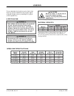
Summary of Contents for SnowEx HELIXX 1.5 yd3

Page 1: ...0 4 5 6 0 yd Installation Instructions CAUTION Read this document before operating or servicing the spreader These installation instructions are for SnowEx HELIXX stainless steel hopper spreaders wit...

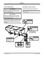
Page 2: ...AFETY WARNING CAUTION LABELS Become familiar with and inform users about the warning and caution labels on the spreader NOTE If labels are missing or cannot be read see your sales outlet CAUTION Indic...

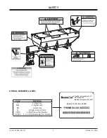
Page 3: ...ZZZZ 5 to 7 Digit Assembly Part Number Shut off control and unplug spreader before servicing ROTATING AUGER CAN CAUSE SERIOUS INJURY OR DEATH Keep arms hands and loose clothing away from auger D6335 D...

Page 4: ...section to determine maximum volumes of spreading material CAUTION During the hopper installation we recommend the addition of an OSHA compliant Backup Alarm This alarm is required for OSHA governed...

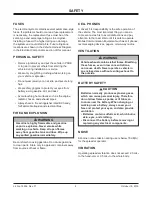
Page 5: ...Gasoline is highly flammable and gasoline vapor is explosive Never smoke while working on vehicle Keep all open flames away from gasoline tank and lines Wipe up any spilled gasoline immediately CELL P...

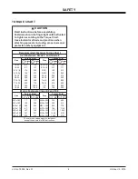
Page 6: ...8 5 67 107 7 7 613 778 1139 1545 450 428 562 796 1117 M33 x 3 50 M36 x 4 00 2101 2701 1468 1952 325 M16 x 2 00 231 167 M18 x 2 50 318 222 Recommended Fastener Torque Chart Size Size Torque ft lb Grade...

Page 7: ...age Do not exceed GVWR or GAWR as found on the driver side cornerpost of vehicle WARNING New untitled vehicle installation of a spreader requires National Highway Tra c Safety Administration altered v...

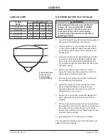
Page 8: ...cle weight GVW 5 Subtract the GVW from the GVWR to determine the available material payload 6 Obtain the weight per cubic yard lb yd of the desired material Divide the weight into the payload to deter...

Page 9: ...Gross Vehicle Weight Rating GVWR lb 11 000 E Gross Vehicle Weight GVW empty lb 7402 F Payload Available lb 3598 G Material Density lb yd 2160 H Maximum Volume yd 1 7 I Maximum Material Fill Level app...

Page 10: ...the steel sheaths that are installed in the fork pockets by removing the 5 16 hardware UNPACKING THE SPREADER Remove 5 16 hardware Steel Sheath Steel Sheath 2 Remove and discard all other shipping du...

Page 11: ...ide must be used when lifting 3 0 4 5 and 5 0 yd hoppers b Remove the top screens Using slings or chains lift the spreader by the four diagonal corner rails and move it into the vehicle bed CAUTION Be...

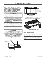
Page 12: ...pockets using at least one fastener per fork pocket Use 1 2 hardware as required by the vehicle application NOTE If the mounting holes are not directly over the vehicle box supports the vehicle bed m...

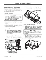
Page 13: ...k pins found in the parts box to attach the spinner drive assembly to the chute supports Install the top lock pin first using the lower holes in the chute supports Secure each locking pin with a cotte...

Page 14: ...vehicle 5 Route the vehicle battery cable as laid out in Step 4 6 Using cable ties secure the battery cable to the vehicle Verify that the harness cannot drop onto the road when it is disconnected fr...

Page 15: ...ny hot sharp or moving parts of the vehicle Routing will vary from vehicle to vehicle 3 Choose a cab control mounting location that can be reached by the harness The location must be within easy reach...

Page 16: ...ys use the tap provided by the OEM DO NOT splice the orange wire into the wire coming o the stoplight switch by the brake pedal Splicing at the stoplight switch may a ect transmission shifting cruise...

Page 17: ...air Cable 4 ga Red 18 ga Black 4 ga Black Connect to spreader harness To Vehicle CHMSL Signal tap located in cab To Vehicle CHMSL Signal tap located in rear of vehicle Not Used 100A Fuse 6 ga Red 18 g...

Page 18: ...P N FEED POS NEG RED B L U BL K RED BLK RED BLK BLK WHT Auger Motor Spreader Harness Assembly ACC Tap ACC Power Block cover removed CHMSL Spreader Module Spinner Motor Vibrator A u g e r M o t o r ELE...

Page 19: ...cured away from hot or moving parts Verify that the vehicle battery cable has su cient ground clearance when the spreader is removed from the vehicle Verify that the CHMSL is properly wired and in wor...

Page 20: ...for spreaders Do not exceed vehicle ratings with a spreader This product is manufactured under the following U S patents 7 400 058 7 737 576 and other patents pending TrynEx International o ers a lim...

Reviews: