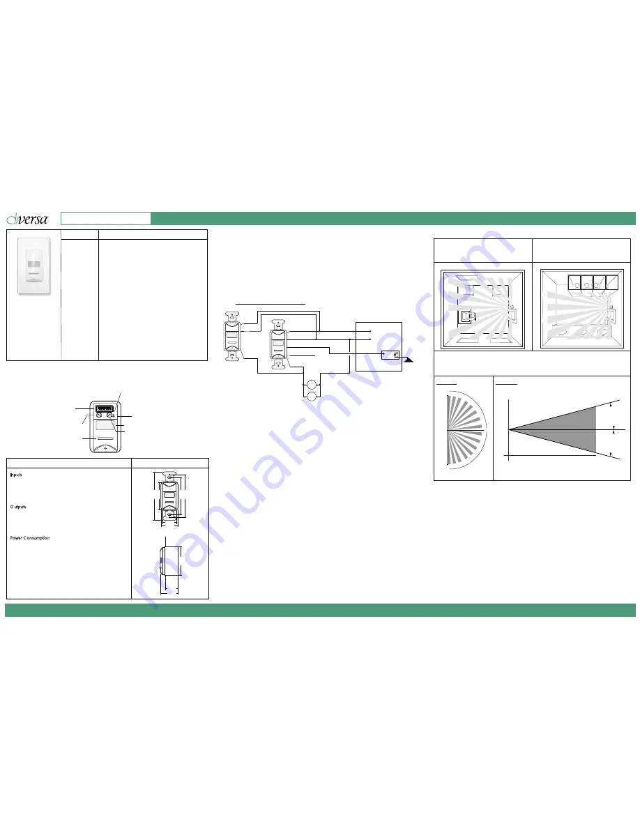
2.56 (65)
3.25 (83)
3.81 (97)
1.25 (32)
4 (101)
1.62 (41)
*Faceplate not included
PART NO.
FEATURES
WOSSID1-P-VW
PIR, 24Vac, 1-pole,
photo, white
WOSSID2-DP-VW
PIR, 24Vac, 2-pole,
dimming, photo, white
WOSSID2-DP-VI
PIR, 24Vac, 2-pole,
dimming, photo, ivory
WOSSID2-DP-VG
PIR, 24Vac, 2-pole,
dimming, phote, grey
• Commercial grade components for long term reliability
• Straightforward wiring for quick installation
• Factory configured for the most common applications
• DIP switches and dials for advanced functionality
• Available in White, Ivory, Grey
• Options: Dimming Control, Photo Sensor
DIMENSIONS - inches (mm)
SPECIFICATIONS
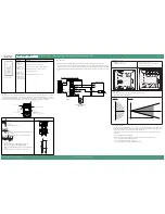
Wiring Diagrams
Diversa 24Vac sensors include #22 AWG wiring leads. Use appropriate sized wire nuts for connecting wires.
CAUTION: Turn power OFF at the circuit breaker before working on sensor. According to NEC 240-83(d), if the branch
circuit breaker is used as the main switch for a fluorescent lighting circuit, the circuit breaker should be marked SWD.
All installations should be in compliance with National Electric Code (NEC) and all state, provincial, federal, and local
codes.
Operation
Low voltage sensors are powered by 24Vac from either the Diversa Series Power Pack (WP-PP20-***) or a 24Vac
transformer. When in operation the sensor will detect initial motion using Passive Infrared (PIR); once motion is
detected, the internal and Power Pack (or connected diode pulse relays) contacts will close. Motion through PIR is
used to maintain the occupied condition as long as occupants remain within coverage pattern of Sensor.
Inputs
•
24Vac + _ 25%
•
Class 2 Low Voltage Source
•
60 Hz
•
#18 AWG
O utputs
•
Diode Pulse: Each outputis capable of driving up to four
Diode Pulse relays.
•
0
-
10V Dimming: Connections are polarity sensitive.
Up to 25mA sinking.
Power C onsumption
•
9.5mA Standard
Manual Override Button
DIP Switches
Time Delay Dial
Ranges from 30s to 30 min.
Full tur
n Clockwise for Auto
Time
Full turn Counterclockwise for test mode
A
uto
Test
Test Mode
Lo
H i
1
5
30
20
Light Level Dial
Photo sensor “P”
models only
Automatic Timeout Mode LED
Sensor
Test Mode LED
Environment
• Indoors, stationary, non-vibrating, non-corrosive
atmosphere and non-condensing humidity
• Ambient Operating Temperature: 32°F to 104°F (0°C to
40°C)
• Storage Temperature: -14°F to 140°F (-25°C to 60°C)
2.65 (68)
1.18 (30)
1.69 (43)
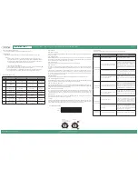
Installation Coverage
Installing in
Offices
•
PIR Re
q
uire
s
Line o
f
Sight
Installing in
Restrooms
• Use 2-pole model to control two loads in
restroom (e.g. light and fan)
Typical Office
Typical Restroom
Standard Lens
•
Optimal u
sa
ge i
s
to detect
s
mall motion
s
s
uch a
s
hand movemen
ts
•
De
s
igned
f
or a mounting height o
f
4f
t
Top View
Side View
15 ft
7.5 ft
0 ft
7.5 ft
15 ft
180º
15º
15º
4 ft
0 ft
8 ft
0 ft
Sensor Location Guidelines
To optimize the performance of Diversa Sensors, please review the coverage pattern, range, and model to
match with the application. Room dynamics will change when people and furniture are occupying the space.
In some rooms, after move in, some sensors may require adjustments.
• Ensure that the sensor is at least 30 inches away from air handlers/registers and not pointed directly at
windows
Sensor Location Guidelines for “P” models
• Place outside the direct cone of light from fixtures and between 3 to 12 feet from a window
• As close as possible to the fixture being controlled
• Above the least illuminated space in the work area
• Away from lighting that is not being controlled by the sensor
15 ft
Wiring to a Power Pac
k
Black
White
Orange
Sensor
Link
WP-PP20-D
Override / Multi-Level
Switching
Black
White
Black
White
Red
Red
Red/White
Orange
Sw
Sw
Line Voltage Passive Infrared (PIR) Occupancy / Vacancy Sensor
Installation Guide
Diversa Occupancy & Vacancy Sensors - Wall Switch, Passive Infrared (PIR), 24Vac
14040400-C
www.douglaslightingcontrols.com
Diversa by Douglas Lighting Controls


