background image

                                                                                            Frame and Door Installation Manual 103 Series 

TITLE:


99-18745 -I001 

– 

Frame and Door Installation Manual Pass-Thru Series 

Manual


REV.


C


Page 

 2 

of 21 

2

17 


Applicable Models 

Pass-Thru Series 

103B, 103N, 403B, 403N, 403I, 403W, 213Z,23ZN, ELC3,EL13,103T 


Copyright © 2021 by 


ALL rights reserved. Information in this document is subject to change without notice. Companies, names and data used in 
examples herein are fictitious unless otherwise noted. No part of this document may be reproduced or transmitted in any form 
or by any means, electronic or mechanical, for any purpose, without express permission of Anthony Manufacturing Co., Inc. 
 

Anthony products identified in this manual are designed and certified to meet 

 or          for safety, and 

for 

sanitation standards. 

European products meet  

  requirements. 

Each customer is responsible for final site approval. 

Summary of Contents for Anthony Complete 103B

Page 1: ...Frame and Door Installation Manual Pass Thru Series Rev C 2022 99 18745 I001 ...

Page 2: ...ject to change without notice Companies names and data used in examples herein are fictitious unless otherwise noted No part of this document may be reproduced or transmitted in any form or by any means electronic or mechanical for any purpose without express permission of Anthony Manufacturing Co Inc Anthony products identified in this manual are designed and certified to meet or for safety and f...

Page 3: ...tructions will ensure proper frame installation 5 2 3 Shimming Frame 5 6 2 4 Sealing the frame 7 8 2 5 Frame Electrical Wiring Connections 9 3 DOOR INSTALLATION 10 3 1 To Install the Door Assembly 10 3 2 To Remove the Door Assembly 10 3 3 To Reverse the Door Swing 11 3 3 1 Frame 11 3 3 2 Door 12 4 TORQUEMASTER AND SAG ADJUSTMENT 15 5 SECTION 5 COOLER FREEZER STORE CONDITION REQUIREMENTS 16 Table 5...

Page 4: ... 32 Hex Key Wire stripper and cutter Soldering iron Heat Gun Razor Knife Plywood Shims Measuring Tape 1 3 Tips Complete replacement of wire assemblies is recommended whenever required Splice wires only if necessary using proper materials such as electrical tape wire nuts flux core solder and heat shrink Apply liquid soap to rail plastic covers and gaskets upon installation to facilitate insertion ...

Page 5: ...g Frame Flap is fully engaged the to Sill Header and Jack Studs creating a seal without any gaps see Figure 2 0 3 Make sure to DO NOT force the frame if the fit is too tight doing so may cause you to break the Sealing Frame Flap or tweak the Frame 4 Insert a mounting screw into a mounting hole in each corner of the frame and tighten each screw until it is approximately a quarter inch from flush 5 ...

Page 6: ...th 4 Install the shim using the same type of mounting hardware that will be used to install the frame Be certain that the shim installation hardware will not interfere with the frame installation hardware 5 If necessary cut a second shim to the same length and install it in the opposite side of the net opening 6 If the adjacent sides of the net opening need to be shimmed repeat the previous steps ...

Page 7: ...is too tight 4 Insert a mounting screw into a mounting hole in each corner of the frame and tighten each screw until it is approximately a quarter inch from flush 5 Check the frame is aligned properly or square Refer to Figure 2 Frame Installation Reference When the threshold is desired drill and lag on pre drilled mounting holes only NOTE Use caulk and food grade silicone sealant to seal the gap ...

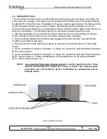
Page 8: ...re flange around the Frame DO NOT remove this foam it is critical to ensure proper insulation 2 Ensure that the Sealing Frame Flap is fully engaged the to Sill Header and Jack Studs creating a seal without any gaps 3 Ensure that any excess shimming material is removed as instructed above in Shimming Frame 4 If your installation is similar to Example 1 in Figure 2 0 proceed to seal with Silicone Se...

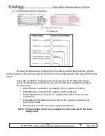
Page 9: ... Using wire connectors these wires should be grouped by the Hot wires Circuit wires the Neutral wires and the ground wire for connection to either the facility or the case power Blue White wire connects to the supplied Hot or Lights Circuit Wire White Blue wire connects to the supplied Light neutral wire Red and Black wires connect to the supplied Hot or Door Frame Heater Circuit Wire White Red an...

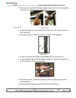
Page 10: ...INSTALLATION 3 1 To Install the Door Assembly 1 Hold the door on each side with the handle facing forward Lift door align torque rod to insert into TorqueMaster socket at base of frame Insert Torque Rod 2 Engage door with hinge pin inserted into Gib hinge pin plug receptacle at top of frame Push door into frame until hinge pin snaps in place Connect Hinge Pin ...

Page 11: ...ing and correct the door alignment by adjusting the TorqueMaster See TORQUEMASTER AND SAG ADJUSTMENT NOTE Exercise caution when handling the door NOTE DO NOT use power tools when adjusting the TorqueMaster NOTE DO NOT over tighten hold open bolt Verify hold open does not bind while sliding along the hold open bolt Adjust as necessary 3 2 To Remove the Door Assembly 1 Release tension on TorqueMaste...

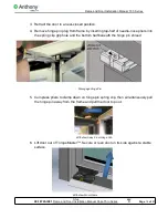
Page 12: ... inserting top half of needle nose pliers into the spring clip grip hole and the bottom half beneath the hinge pin shroud Disengage Hinge Pin 5 Compress pliers to clamp down on hinge pin spring clip then simultaneously pull the hinge pin away from the frame and pull the door top out Withdraw Away From Hinge Gib 6 Lift door out of TorqueMaster Secure or lean door on its side against a stable surfac...

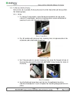
Page 13: ...rquemaster and turn mounting screw counter clockwise for less than turn Lift Torquemaster off frame Remove TorqueMaster 2 Pry off underneath plug cap from mounting hole on opposite side of the doorframe with a flat head screwdriver Remove Plug Cap 3 Set Torquemaster on opened mounting hole Align the flanged corners of the mounting tabs with the SAG ADJUSTMENT screw facing the inside of the frame M...

Page 14: ...nge pin wire connections in the rail on the hinge side of the door assembly 2 Disconnect the Hot Neutral and Ground wires of the hinge pin Hinge Pin Wire 3 Loosen and remove the hinge pin assembly from the top door rail 4 Using a plastic mallet and a flat head screwdriver remove the torque rod from the bottom of the door assembly Remove Torque Rod 5 Reinstall the hinge pin and the torque rod into ...

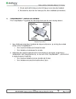
Page 15: ...e door alignment and the door closing tension Remove Torque Rod 1 Use a flathead screwdriver to adjust the torque rod tension by turning the outside screw on the TorqueMaster Turn counter clockwise to increase tension Turn clockwise to decrease the tension 2 Adjust the door sag to square the door in the frame by turning the screw that is marked SAG ADJ sag adjustment on the end of the TorqueMaster...

Page 16: ...he recommended temperatures Refer to Table 6 1 Operating conditions above Evaporators must be equipped with defrost termination control to end the termination early if the coil is cleared Recommend scheduling defrost during low traffic periods Adjust the duration of evaporator defrosts according to the manufacturer s recommendations Cooler Freezer must be regularly inspected for air leaks Identifi...

Page 17: ...nual on how to disengage power The use frequency of doors will vary from location to location and the frequency in routine for preventative maintenance will vary for everyone depending on the amount of traffic For Anthony products used in harsh or extreme ambient conditions it is recommended that these inspection intervals be performed on a more regular basis When issues are found please refer to ...

Page 18: ...spect that the Hinge Pin is properly connected with the frame receptacle DO NOT remove the factory installed dielectric grease from the Hinge Pin assembly to ensure the proper function o Inspect that the Hinge Pin and receptacle are rust corrosion free and there is an adequate amount of Dielectric Grease present o If when replacing or servicing Door and it is removed from the Hinge Pin receptacle ...

Page 19: ...routine General Cleaning Regularly clean by wiping down the frame door rails bezels and gaskets by checking for food debris dust and other foreign objects that may prevent the door from closing correctly Use non abrasive cleaning apparatus i e microfiber cloth when wiping down frame and door rails Cleaning Inside Door Glass To clean door glass on the inside of the door We recommend the following c...

Page 20: ...vers on frame mullions No Power to Frame Check Power Supply Adjust energy controller to Full On Replace Power Supply Replace Energy Humidity Controller Replace Hinge Pin Replace wiring Check energy humidity controller Check hinge pin connections Check glass wire connections Check hinge pin wiring Low Voltage Check main voltage Adjust energy controller to Full On Replace Frame heater wires Check hu...

Page 21: ...n hinge pin socket Facility or case not level Frame not properly shimmed Hold open binding damaged Lamp inoperative Power switch OFF Turn power switch ON Lamp burned out Replace lamp Lamp failure Check socket mounting Check socket lamp connection Check ground wire connection Incorrect lamp Replace with correct lamp Ballast failure Check wire connections Replace ballast Incorrect ballast Replace ba...

Reviews: