TL 1128 (TOP HOLES)
Issued August 2016
Revision No: 006
Printed in U.S.A.
Copyright 2016, Bayne Premium Lift Systems
Actuator Assembly Instructions
17
ACTUATOR ASSEMBLY INSTRUCTIONS
1100 Series Roller Bearing Actuator, Part Number 1122-1026 ( WI-1125-C )
Licensed under on or more of the following U.S. Patents: 4,773,812 1,327,765 5,308,211 5,333,984
NOTICE
READ INSTRUCTIONS COMPLETELY BEFORE STARTING ASSEMBLY.
Before starting the assembly of the Rotary Actuator, refer to the exploded parts drawing and parts list (Figure A-13 found at
the end of these instructions) to familiarize yourself with the individual components. Prepare a clean surface, in an area
free of blowing dust and contaminants in which to assemble the Rotary Actuator. Be sure that all parts are thoroughly clean
and dry before starting assembly.
NOTICE
All torque values given apply to clean dry threads only. Follow these directions closely when repairing the Rotary Actuator.
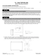
1. Install the piston seal load ring (13) ( Figure C-1 ) in the small groove on the head of the actuator rack (2). Place the
“square” piston seal (17) over the load ring (13) in the same small groove (a small “blunt” flathead screwdriver may
be used, taking care not to scratch or damage the seal). Install the wear ring (18) in the large groove on the head of
the rack. Using a ring compressor, firmly seat the rings on the rack before setting it aside, this will help to reverse the
effects of any stretching of the rings that occurred during installation. Repeat this procedure for the other rack.
Figure C-1
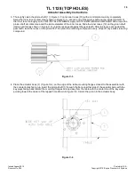
2. Install the tube seal (12) ( Figure C-2 ) and “square” tube seal backup (16) on each end of the actuator tubes (3)
( Figure C-13 ). Be sure that the “square” tube seal backup ring is toward the inside of the tubes at both ends as
shown. Press all rings firmly into the grooves. Repeat this procedure for the other tube.
Figure C-2


