TL 1128 (TOP HOLES)
Issued August 2016
Revision No: 006
Printed in U.S.A.
Copyright 2016, Bayne Premium Lift Systems
Actuator Assembly Instructions
18
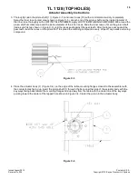
3. Thoroughly clean the pinion shaft (1) ( Figure C-3 ) and inner races (10) with a mild solvent and dry completely.
Spray the inner race contact area (shown in Figure C-3 ) at each end of the pinion shaft and the inside diameter of
the inner race thoroughly with LOCTITE 7649 N PRIMER. Apply LOCTITE RETAINING COMPOUND 609 around the
pinion shaft at contact area and the inside diameter of the inner races. Slide the inner races (10) on the pinion shaft
(radius end first as shown in Figure C-3) until the races seat against the gear teeth. After the races seat against the
gear teeth, twist the races on the pinion 360º to spread the retaining compound evenly. Wipe off any excess retaining
compound.
Figure C-3
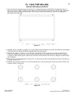
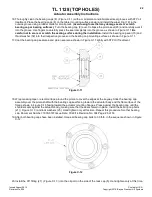
4. Place the actuator body (7) ( Figure C-4 ) on the edge of the table, mounting flanges closest to the assembler with
the counter-bores facing up. Insert the pinion shaft (1) through the bore on either side of the actuator body with the
key ways facing back toward the mounting flanges and up away from the table with the center line of the key ways
pointing toward the center of the tapped hole shown in Figure C-4. Center the pinion in the actuator body.
Figure C-4


