TL 1128 (TOP HOLES)
Issued August 2016
Revision No: 006
Printed in U.S.A.
Copyright 2016, Bayne Premium Lift Systems
Actuator Assembly Instructions
23
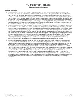
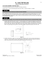
21.Install the 45° bulk-head fitting (31) ( Figure C-13 ) up through the hole in the tube mounting bracket (30) bolted to
the tube cap as shown in Figure C-13. The 45° end must be pointing down away from the rack cap (5) and back
toward the mounting flanges on the actuator body. Hand tighten only at this time.
22.Install the rack cap extension tube assembly (29) ( Figure C-13 ) between the 90° fitting in the rack cap and the 45°
fitting in the tube mounting bracket as shown in Figure C-13. Tighten all connections.
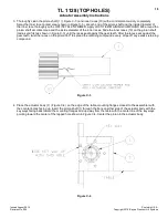
23.Install the orifice plug (11) ( Figure C-13 ) into the oil port on the side of the tube cap (4), and install the 90° fitting
(27) into the oil port over the orifice plug as shown in Figure C-13. Turn the fitting so that it points down away from
the rack cap (5) and back toward the mounting flanges on the actuator body and tighten.
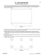
24.Install the cap nuts (28) ( Figure C-13 ) onto the open fittings to prevent contamination of the unit until the hoses are
installed.


