OM/SM-AH-CE
18
The gas burners are protected by an
electronic flame failure device which
incorporates automatic ignition of the
burners and instant shut-off of the gas
supply to the burners should a gas supply
interruption occur.
Options available with listed models are:
1.
Three inch (7.6 cm) tangent draw-off
valve. (Factory-installed option)
2.
Basket inserts.
3.
Water filler with swing spout and
bracket.
4.
Kettle brush kit.
5.1.2
Operational and Maintenance Safety
CAUTION
BE SURE ALL OPERATORS READ,
UNDERSTAND AND FOLLOW OPERATING
INSTRUCTIONS, CAUTIONS AND SAFETY
INSTRUCTIONS IN THIS MANUAL.
WARNING
INSTALLATION OF THE UNIT MUST BE
DONE BY PERSONNEL QUALIFIED TO
WORK WITH ELECTRICITY, GAS AND
PLUMBING IN ACCORDANCE WITH ALL
APPLICABLE CODES.
BEFORE REPLACING ANY PARTS,
DISCONNECT THE UNIT FROM THE
ELECTRIC POWER SUPPLY AND CLOSE
THE MAIN GAS COCK. ALLOW FIVE
MINUTES FOR UNBURNED GAS TO VENT.
TO PREVENT SHOCKS, ALL APPLIANCES
WHETHER GAS OR ELECTRIC, MUST BE
EARTHED.
5.2 Lighting and Operation
5.2.1
Initial Kettle Lighting and Operational
require venting. (This will require a
Readiness Check
service call).
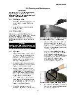
After the AH Kettle has been installed according
6.
Switch the On/Off switch to the "On"
to service and installation instructions, perform
position. The "power on" neon will
initial start-up as a test to ensure that the unit is
illuminate.
operating correctly. Follow the steps below.
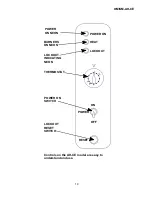
Refer to the picture for identification of AH
7.
Turn the thermostat dial to the required
controls and indicators.
setting.
1.
Remove all literature and packing
8.
After 10-15 seconds the burners should
material from the interior and exterior of
light. The "burners on" neon will
the unit.
illuminate.
2.
Make sure gas and electricity supplies
9.
In the event the burners do not light, or
are switched on.
go out as indicated by the illumination of
3.
Ensure that the kettle is filled with water
off. Wait approx 1 minute. Press lockout
before lighting.
reset switch and repeat steps (4) to (8).
4.
Check the water level in the jacket. The
level should be between the lines on the
gauge glass. If the level is low, the
jacket water level will be required to be
topped up. (This will require a service
call).
5.
Check the pressure gauge. If the gauge
does not show sufficient vacuum (that is,
20 to 30 below zero), the jacket will
the lockout indicating neon, turn the unit
WARNING
AVOID CONTACT WITH THE FLUE.
SURFACES ARE VERY HOT AND WILL
CAUSE BURNS.
DO NOT OBSTRUCT FLUE EXHAUST
OPENING.
Summary of Contents for GROEN AH-20
Page 23: ...OM SM AH CE 23 ...
Page 24: ...OM SM AH CE 24 Parts Lists ...


