background image

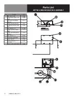
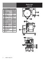
22 OM-DHS(/T)-40(C,A,C2T™)

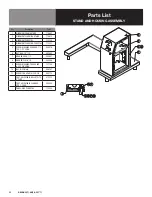
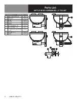
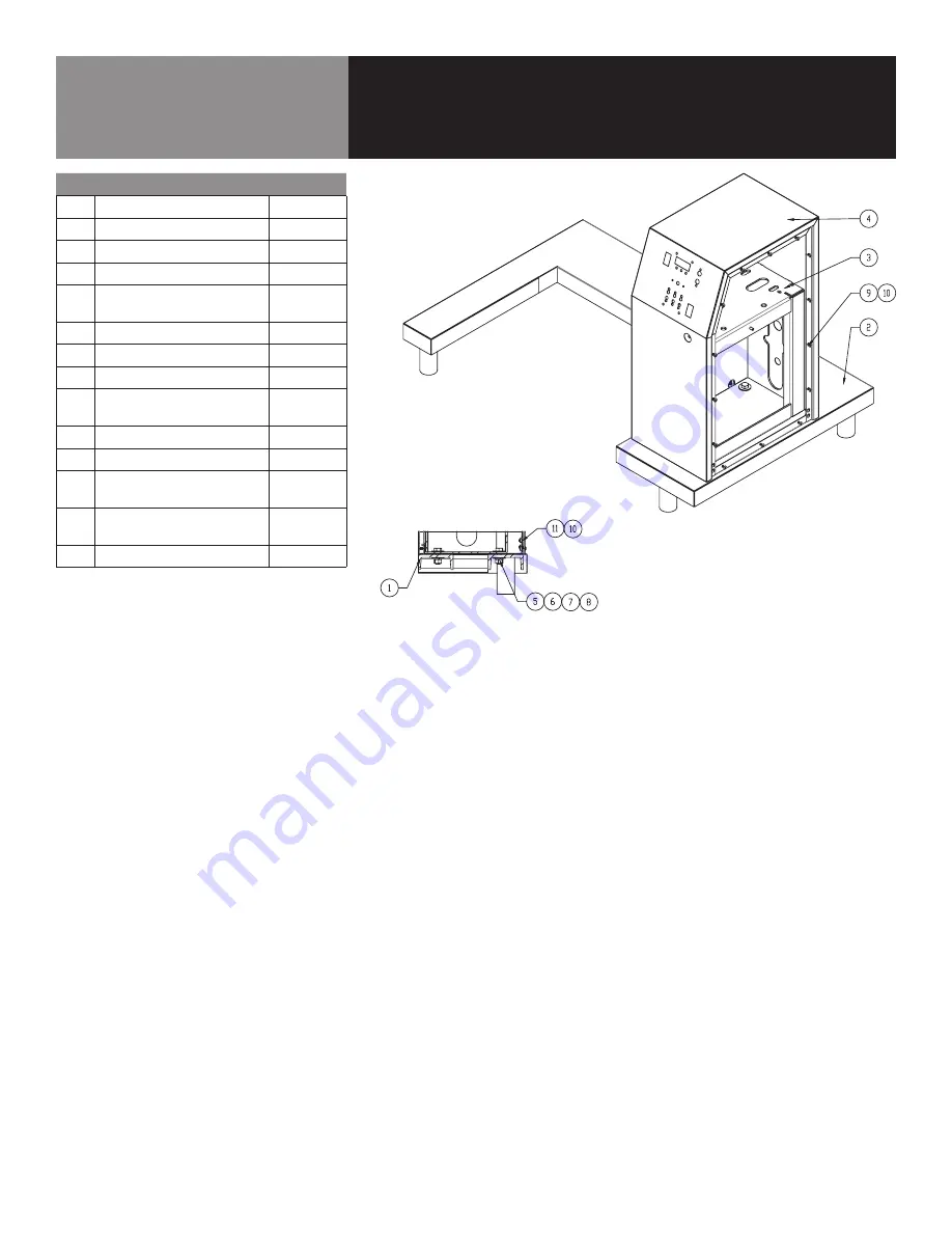
Parts List

STAND AND HOUSING ASSEMBLY

Key

Description

Part #

1

WELDMENT, FRAME, STAND

174802

2

WELDMENT, CLADDING, STAND

174812

3

WELDMENT, PEDESTAL

175330

4

WELDMENT, CLADDING, PEDESTAL

175337

5

SCREW, MACHINE, HEX HEAD, 1/2-
13 X 1-1/2" LONG

008679

6

NUT, HEX, 1/2"-13

005603

7

WASHER, LOCK, 1/2

005657

8

WASHER, PLAIN, 1/2

005049

9

SCREW, MACHINE, TRUSS HEAD 
8-32 X 3/8" LONG

137766

10

Nut, 10-32 Weld

069791

11

SCREW, TRS HEAD 10-32 X 3/8

004173

-

FOOT, ADJUSTABLE, BULLET-FITS 
2" TUBE

013275

-

FOOT, ADJUSTABLE, FLANGED-
FITS 2" TUBE

096569

-

PANEL, SIDE, PEDESTAL

175336

Summary of Contents for Groen DHS-40A

Page 1: ...inless steel pan els enclose the controls and the base A u shaped frame with four stainless steel tubular legs support the unit Bullet feet on each of the legs can be adjusted to level the kettle Models with a T suffix are supplied with a two inch tangent draw off valve The self contained steam source is heated by propane or natural gas Electronic spark to pilot ignition is standard for all units ...

Page 2: ...EF VALVE DIRECT CONTACT COULD RESULT IN SEVERE BURNS WARNING TO AVOID INJURY READ AND FOLLOW ALL PRECAUTIONS STATED ON THE LABEL OF THE WATER TREATMENT COMPOUND WARNING BEFORE REPLACING ANY PARTS DISCONNECT THE UNIT FROM THE ELECTRIC POWER SUPPLY AND CLOSE THE MAIN GAS VALVE ALLOW 5 MINUTES FOR GAS TO VENT CAUTION USE OF ANY REPLACEMENT PARTS OTHER THAN THOSE SUPPLIED BY GROEN OR AUTHORIZED DISTRI...

Page 3: ...ket to help improve bond strength After application the bond strength will increase as the adhesive flows onto the surface At room temperature approximately 50 of the ultimate strength will be achieved after 20 minutes 90 after 24 hours and 100 after 72 hours 7 Bring electrical service through the entrance at the rear of the support housing with a inch conduit connector Make a watertight connectio...

Page 4: ...as shut off valve supplies inlet gas to the unit b Lighted Power ON switch located on the control console Controls main power to the unit c The temperature knob located on the control console is used to set the kettle heat values between 1 0 and 10 0 The current setting will be reflected on the display d Heating indicator light located on the control console lights when the controller sends call t...

Page 5: ...led i Ready alarm The control will sound 3 beeps when the unit has reached within 20 degrees of set point during pre heat and when a higher unit temperature is selected j AUTO C2T Button Enables the user to select a set product temperature between 100 F and 230 F using the temperature knob and display The operator will press the AUTO C2T button and then select the set product temperature using the...

Page 6: ...l notify the user that attention is required Simply plug the core probe back into the receptacle and the cook process or Hold Mode will continue e While the core probe is not in use ensure the sealing cap is properly protecting the panel mount connector Failure to properly use the sealing cap could result in damage to the unit OPERATING PROCEDURE 1 To Start Kettle Heating a EVERY DAY make sure tha...

Page 7: ...GLOVES LES OR FACE SHIELD AND ECTIVE CLOTHING READ THE NINGS AND FOLLOW THE TIONS ON THE LABEL OF THE NER CAREFULLY edure Clean food contact surfaces as soon as possible after use If the unit is in continuous use thoroughly clean and sanitize the interior and exterior at least once every 12 hours WARNING ANY DIRECT CONTACT WITH HOT ACES DIRECT SKIN CONTACT D RESULT IN SEVERE BURNS Scrape and flush...

Page 8: ...ence of discharge or the valve leaks stop using the kettle and contact a qualified Groen service representative 5 Keep the primary burner gas jet air inlets free of dust and lint 6 The pilot flame should be blue It should envelop about inch 12 mm of the flame sensor tip 7 The gear housing has fittings for lubrication of moving parts The gears do not run in oil so periodic lubrication with grease i...

Page 9: ...ated with a jumper wire to verify that the component is faulty If this determination is made contact a certified Groen Service Agency for assistance SEQUENCE OF OPERATION The following action reaction outline is provided to help understand how the kettle works 1 When the power switch is turned on it starts the spark igniter and opens the automatic valve for the pilot burner The spark ignites a pil...

Page 10: ... temperature of the kettle X e That tilt limit switch is closed when body is not tilted X System does not produce a spark Auth Service Rep Only a AC voltage between terminals on secondary side of transformer If it is not 24Volt replace the transformer X b That the high tension cable is firmly attached and in good condition If cracked or brittle replace X c Pilot electric ceramic for crack or break...

Page 11: ...69 3 FOOT ADJUSTABLE BULLET FITS 2 TUBE Z013275 4 ASSEMBLY TILT MECHANISM Z045752 5 ASSEMBLY SUPPORT BRACKET GAS LINE Z068132 6 VALVE GAS MANUAL SHUTOFF 1 2 NPT Z098458 7 KNOB THERMOSTAT DIAL 175095 8 ASSEMBLY TILT SWITCH 135331 9 RELIEF VALVE WITH GAUGE 139395 10 PIPING ASSEMBLY WATER FILL 139396 11 KETTLE ARM IGNITION MODULE BOX ASSEMBLY 123734 12 COMPONENT BOX 175337 ...

Page 12: ... 2 LONG Z008679 9 HOUSING BEARING ASSY Z009762 10 BEARING BALL Z009765 11 GEAR WORM 3 4 BORE Z012026 12 SHIM 0 01 THICK Z012039 13 SCREW SET SOCKET 5 16 18 1 2 LONG Z012060 14 PIN ROLL 1 4 DIA 1 1 4 LONG Z012614 15 RING INTERNAL RETAINING Z013483 16 GEAR 3 BORE 92 TEETH Z013609 17 HANDLE CRANK 3 4 BORE Z013617 18 SHAFT HANDLE 3 4 Z013624 19 SPACER SCHEDULE 40 3 Z013625 20 SHIM TRUNNION 16 GA Z0882...

Page 13: ...A C2T Parts List GAS LINE SUPPORT BRACKET ASSEMBLY Key Description Part 1 WELDMENT SUPPORT BRACKET GAS Z068133 2 NUT HEX SERRATED 1 4 20 NT1101 3 STRAP CONDUIT 3 4 EMT 135252 4 SCREW CAP HEX HEAD 1 4 20 3 4 LONG Z005609 ...

Page 14: ...UT 101145 SPACER LIGHT MOUNT 175221 BRACKET LIGHT MOUNT 175222 Parts List DHS FRONT PANEL ASSEMBLY For Advanced Control Models Key Description Part 1 2 ALUMINUM KNOB 174829 2 POWER SWITCH 176921 3 INDICATOR LIGHT RED 116383 4 C2T CONTROLS 176895 5 HEX NUT 101145 6 INDICATOR LIGHT AMBER 116384 SPACER LIGHT MOUNT 175221 BRACKET LIGHT MOUNT 175222 OVERLAY C2T CONTROL 176891 CAP SOCKET PANEL MOUNT COR...

Page 15: ... 4 SCREW ROUND HEAD 4 40 3 4 LONG Z003122 5 NUT HEX KEPS 4 40 Z071297 4 4 3 2 1 5 5 Parts List RELIEF VALVE WITH GAUGE Key Description Part 1 VALVE SAFETY 50 PSI 1 2 NPT Z097005 2 GAUGE COMPOUND PRESSURE DUAL SCALE Z084208 3 ELBOW STREET 90 DEG 1 2 NPT CHROME PLATED Z010108 4 ASSEMBLY PLATE CHAIN ASM Z008332 5 ASSEMBLY RELIEF VALVE PIPING 141428 3 1 4 2 5 ...

Page 16: ... 2 ELBOW STREET 90 DEG 1 2 NPT Z004185 3 NIPPLE CLOSE 1 2 NPT Z008877 4 BUSHING REDUCING 1 2 NPT Z008739 Key Description Part 1 ELBOW STREET 90 DEG 1 2 NPT Z004185 2 NIPPLE CLOSE 1 2 NPT Z008877 3 VALVE SWING CHECK Z004187 4 PLUG PIPE 1 2 NPT SQUARE Z011146 Parts List WATER FILL ASSEMBLY 3 1 2 4 1 2 3 2 4 ...

Page 17: ...GNITION MODULE 123775 4 GASKET SPARK IGNITION BOX 104941 5 IGNITION MODULE GAS SPARK 25V Z085153 6 NUT HEX KEPS 6 32 Z071289 7 CONDUIT ADAPTER PLASTIC MALE 123733 8 COVER ENCLOSURE IGNITION MODULE 104948 9 NUT HEX KEPS 8 32 Z069784 10 TIE ANCHOR SCREW MOUNT 102231 11 STRAP CABLE TIE Z011093 12 SCREW BINDER HEAD 10 32 3 8 LONG Z084201 CABLE HI VOLT SPARK IGNITION Z096728 ...

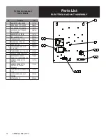
Page 18: ... KEPS 10 32 Z071256 7 TERMINAL BLOCK 2 POLE Z003887 8 FUSE HOLDER TYPE 3 AG Z077854 9 FUSE TYPE 3 AG Z077853 10 SCREW ROUND HEAD 8 32 1 1 4 LONG Z005056 11 TRANSFORMER 20 VA 120 24V 137487 HARNESS WIRING PANEL CTRL 123582 WIRE HARNESS CONTROL PANEL DH CLASSIC ADVANCED 175839 HARNESS WIRING KETTLE CONTROL 123779 HARNESS WIRING KETTLE CONTROL DH CLASSIC ADVANCED 175367 LABEL ELECTRICAL CONNECTION 11...

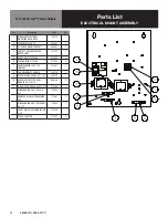
Page 19: ... 122192 1 5 FUSE 3 0 AMP TYPE 3 AG 077853 2 6 FUSE HOLDER TYPE 3 AG 077854 2 7 TRANSFORMER 20VA 120 PRIMARY 137487 2 8 LUG GROUND 14 6 AWG 129714 1 9 SCREW ROUND HEAD 8 32 1 1 4 005056 1 10 SCREW HEX SLOTTED HD W WASHER 8 32 X 3 8 069789 6 11 SCREW ROUND HEAD 6 32X 375 012398 2 WIRE HARNESS CONTROL DH C2T 176929 1 HARNESS HIGH VOLTAGE WIRING TDH 175387 2 WIRE HARNESS CONTROL PANEL DH C2T 176963 1 ...

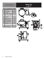
Page 20: ...ING HIGH VOLTAGE Z072140 6 LABEL ELECTRICAL CONNECTION 115V 102229 8 LABEL WARNING Z098171 9 LABEL NSF Z066735 11 OVERLAY DH FRONT PANEL 123802 12 NAMEPLATE DHS KETTLE 139075 13 LABEL WARNING PREHEATING Z095070 14 LABEL TDO VALVE CAUTION 110156 16 LABEL CAUTION Z002723 LABEL WARNING AGA ADDENDA B Z099961 LABEL WARNING CALIFORNIA Z093614 LABEL WARRANTIES VOID Z074816 For Classic Control Models ...

Page 21: ...LABEL WARNING Z072140 6 LABEL ELECTRICAL CONNECTION 115V 102229 7 LABEL WARNING FOR SELF Z098171 8 LABEL NSF Z066735 9 OVERLAY ADVANCED DH DEE 175304 10 OVERLAY CLASSIC DH DEE 175303 11 LABEL TDO VALVE CAUTION 110156 12 LABEL CAUTION Z002723 13 LABEL WARNING Z095070 LABEL WARNING AGA ADDENDA B Z099961 LABEL WARNING CALIFORNIA Z093614 OVERLAY OPERATION INSTRUCTIONS DH 175053 OPERATION OVERLAY ADVAN...

Page 22: ...MENT CLADDING PEDESTAL 175337 5 SCREW MACHINE HEX HEAD 1 2 13 X 1 1 2 LONG 008679 6 NUT HEX 1 2 13 005603 7 WASHER LOCK 1 2 005657 8 WASHER PLAIN 1 2 005049 9 SCREW MACHINE TRUSS HEAD 8 32 X 3 8 LONG 137766 10 Nut 10 32 Weld 069791 11 SCREW TRS HEAD 10 32 X 3 8 004173 FOOT ADJUSTABLE BULLET FITS 2 TUBE 013275 FOOT ADJUSTABLE FLANGED FITS 2 TUBE 096569 PANEL SIDE PEDESTAL 175336 ...

Page 23: ...117013 6 ASSEMBLY BURNER DHS NAT N02 Z090644 6 ASSEMBLY BURNER DHS NAT N24 158125 6 ASSEMBLY BURNER DHS NAT N46 158128 6 ASSEMBLY BURNER DHS NAT N68 158131 6 ASSEMBLY BURNER DHS NAT N810 158134 6 ASSEMBLY BURNER DHS PROPANE P02 Z090628 6 ASSEMBLY BURNER DHS PROPANE P24 158137 6 ASSEMBLY BURNER DHS PROPANE P46 158140 6 ASSEMBLY BURNER DHS PROPANE P68 158143 6 ASSEMBLY BURNER DHS PROPANE P810 158146...

Page 24: ...X SERRATED 1 4 20 NT1101 16 BAR Z005440 17 CLAMP RIGID CONDUIT Z068687 20 COVER BOTTOM Z090630 21 CAP BOTTOM COVER PLATE Z049803 22 GASKET BOTTOM PLATE Z007937 23 SCREW CAP WASHER HEAD SLOTTED 10 32 3 8 LONG Z002962 24 FITTING COMPRESSION 90 DEG 1 4 TUBE TO 1 8 NPT M Z004584 25 TUBE ALUMINUM 1 4 OD 20 LONG Z006796 26 CHAMBER COMBUSTION 122094 COUPLING FULL 1 2 NPT Z005722 FITTING COMPRESSION 5 8 T...

Page 25: ...T Key Description Part 1 LABEL TDO VALVE CAUTION 110156 2 STEM VALVE Z009048 3 BONNET Z009047 5 NUT HEX Z009354 6 HANDLE Z009029 7 KBA TRUNNION NO TDO 143152 8 KBA TRUNNION 2 TDO 143150 1 4 PERFORATED DISK STRAINER 2 TDO Z009044 NUT WING 10 24 Z009028 O RING Z009034 ...

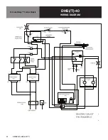
Page 26: ...26 OM DHS T 40 C A C2T DHS T 40 WIRING DIAGRAM For Classic Control Models ...

Page 27: ...27 OM DHS T 40 C A C2T DHS T 40 WIRING DIAGRAM For Advanced Control Models ...

Page 28: ...28 OM DHS T 40 C A C2T DHS T 40 WIRING DIAGRAM For Cook2Temp Control Models ...

Page 29: ...29 OM DHS T 40 C A C2T Service Log Model No Purchased From Serial No Location Date Purchased Date Installed Purchase Order No For Service Call Date Maintenance Performed Performed By ...

Reviews: