1
OM-NHFP
OM-NHFP
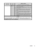
SYMPTOM
WHO
WHAT TO CHECK
•
indicates items which must be performed by an authorized technician.
14
B. Model NHFP with Thermopile Ignition System
Pilot will not light.
User
a.
Lighting procedure, to ensure that the instructions in the
Operation section of this manual are followed
Auth Service
Rep Only
b.
That the pilot gas supply line is purged of air.
•
c.
Pilot gas adjustment screw, to ensure that it is open.
•
d.
Pilot tubing and orifice for clogging.
•
Pilot flame goes out
when Combination
Control knob is
released.
Auth Service
Rep Only
a.
Pilot gas adjustment.
•
b.
That electrical connections from Powerpile generator to
Pilotstat power unit and to Powerpile operator are clean
and secure.
•
c.
Open and closed circuit output voltages of the generator
against the Acceptable Range Charts in the manual for the
W720 Systems Tester.
•
d.
Resistance of the Pilotstat power unit.
•
e.
If an appropriate meter is not available, replace first the
generator, than the power unit.
•
Pan will not heat, and
pilot light is out
User
a.
That the knob on the Combination Gas Control Valve is in
the "ON" position.
b.
Pilot tubing and orifice for clogging.
Auth Service
Rep Only
c.
That electrical connections from Powerpile generator to
Pilotstat power unit and to Powerpile operator are clean
and secure.
•
d.
Open and closed circuit output voltages of the generator
against the Acceptable Range Charts in the manual for the
W720 Systems Tester.
•
e.
If an appropriate meter is not available, replace the
generator.
•
Pan will not heat, but
pilot light is burning.
Auth Service
Rep Only
a.
That high-limit thermostat switch is closed.
•
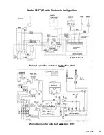
C. Model NHFP(E) with Hot Surface Ignition System (Refer to Schematic)
Burner does not come
on, and glow coil does
not heat.
User
a.
That electric power is being supplied to the unit.
Auth Service
Rep Only
b.
For 115V input to the control module.
•
c.
For a 24V supply at the transformer.
•
d.
For 24V between pins "2" and "4" of the control module. If
not present, check the thermostat/high-limit circuit for open
thermostat switches .
•
e.
Voltage of supply to the igniter by removing the igniter plug
from the receptacle of the control module and reading
voltage across the pins of the igniter receptacle. If 115V is
present, replace the igniter. If 115V is not present, replace
the control module.
•
f.
Voltage across the terminals of the main gas valve
solenoid. If 24 VAC is present, replace the gas valve
assembly. If not, replace the control module.
•


