CASE CONNECTIONS
10
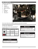
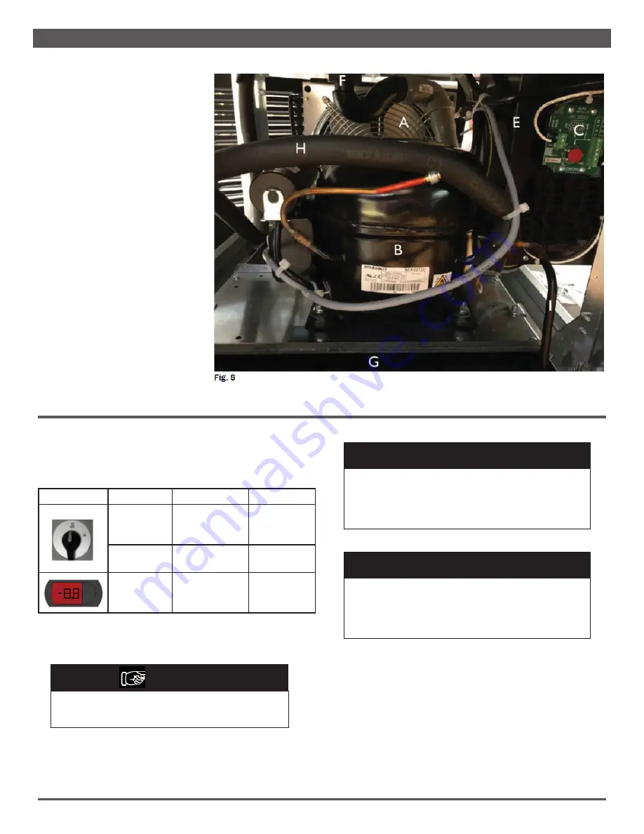
COMPRESSOR COMPARTMENT DIAGRAM
A
.......
Condenser Fan
B
.......
Compressor
C
.......
Fan Control Board
D
.......
Electrical Junction Box
E
.......
Drain
F
.......
Dissipater Pan
G
.......
Suction Line
H
.......
Discharge Line
Note: Access locations and/or compartment configuration will vary based on case design.
CONTROLS ON THE CONDENSING UNIT
The control panel is in the lower section of the cabinet. See
Appendix for full instructions on how to program the Carel
electronic controller.
Picture
Function
Operates On
Adjusts
switch on/off
Power supply
to control panel
thermostat
//
switch on/off
Condensing unit
motor
//
Adjustment
//
Case
Temperature
Defrost cycle
N O T E
See Appendix for full instructions on how to program
the Carel electronic controller.
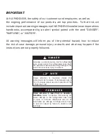
D A N G E R
ALWAYS CHECK THE THERMOSTAT CURRENT
RATING
because it may have a limited current, as low
as 2A. If necessary protect digital thermostat contacts
with a contactor.
▲
!
D A N G E R
When carrying out maintenance tasks inside the
refrigerated case or compressor compartment, it is
essential to disconnect the power source to the case
from the main power.
▲
!
Summary of Contents for Hillphoenix MIDA
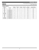
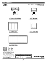
Page 5: ...3 TECHNICAL DATA MIDA Mobile Single Deck Self Contained Mercchandiser 3 X3 4 X4 4 X8 ...
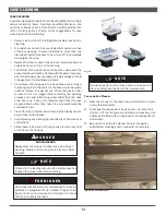
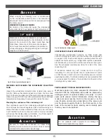
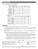
Page 18: ...CASE CLEANING 16 SCHEDULED MAINTENANCE TABLE Fig 17 Recommended Cleaning Schedule ...
Page 26: ...24 PARTS ORDERING THIS PAGE LEFT BLANK ...
Page 36: ... BLANK 34 PARTS LIST MIDA 4x4 MIDA 4x8 PARTS ORDERING NOTES ...
Page 43: ... BLANK 41 PARTS LIST MIDA 3X3 PARTS ORDERING NOTES ...
Page 44: ...42 APPENDIX MIDA 3X3 MIDA 4X4 ...
Page 45: ......
Page 46: ...44 APPENDIX MIDA 4X8 ...
Page 47: ......
Page 48: ...46 MIDA 3X3 WIRING DIAGRAM ...
Page 49: ...47 MIDA 4X4 WIRING DIAGRAM C SERIAL NUMBER ...
Page 51: ... BLANK 49 MIDA 4X8 WIRING DIAGRAM C SERIAL NUMBER ...
Page 52: ... BLANK 50 MIDA 4X8 WIRING DIAGRAM C SERIAL NUMBER ...
Page 54: ...52 MIDA 4X8 WIRING DIAGRAM D SERIAL NUMBER ...
Page 56: ...54 ...

